KENBAK-1 · Volume 14
KENBAK-1 — Volume 14 — My nanoKENBAK-1
Adwater & Stir's pocket-sized, surface-mount KENBAK-1 for the machine's fiftieth anniversary: the board part by part, the circuit as far as it can be read, the rechargeable cell and why it must never be a CR2032, setting the clock, programming it from its keys, reaching its processor through six unpopulated pads, a parts list for repairs, and faults and fixes
14.1 About This Volume
The second of Adwater & Stir’s small KENBAK-1s is the nanoKENBAK-1. It has been sold out since December 2025, and I have put my name on the maker’s e-mail waiting list, so this volume is written ahead of the machine, to be filled in when one arrives beside the µKENBAK-1 of Volume 13 and the full-size TTL machine of Volume 11. “Building” is generous for this one: it arrives assembled and tested, every part surface-mounted by the maker. What is left to its owner is to charge it, set its clock, learn its keys and look after its battery, and, if it ever needs it, to repair it or reach its processor, for which there is no published procedure at all.
This volume covers all of that. It has the same parts as Volume 13 (the board, the circuit, a parts list, programming, faults) but the nanoKENBAK-1 is a different object in almost every practical respect. It has no sockets, no serial port and no regulator; it runs from a rechargeable lithium-ion coin cell; its clock chip is soldered to the board with its own backup cell; and its processor can only be reached through six bare pads. The firmware is the same Mark Wilson emulation, so Volume 13’s tables of key chords, built-in programs and SysInfo calls apply here unchanged and are not repeated.
The maker publishes no schematic and no parts list for the nanoKENBAK-1. Everything here comes from its pages and frequently-asked questions, its 2021 photographs of the board, the maker’s forum, and the data sheets of the parts that can be identified. Inferences are marked as such.
14.2 What It Is
Chris Davis made the nanoKENBAK-1 for the KENBAK-1’s fiftieth anniversary in 2021. He describes seeing the Digirule 2, a programmable ruler made with surface-mount parts, and thinking it “would be really cool if it functioned just like a Kenbak-1”; he converted his µKENBAK-1 board design and “took a stab at creating an SMD device”, a project that “spanned a couple years, several revisions, and fumbling around with solder rework stations and eventually my own reflow oven” (Adwater & Stir, “nanoKenbak-1”).
Table 1 — What It Is
| nanoKENBAK-1 (50th Anniversary) | |
|---|---|
| Size | 8.5 × 1.5 in, the board is the whole machine |
| Processor | Microchip (Atmel) ATmega328P, 32-pin TQFP, surface-mounted |
| Firmware | ”the same ATMEGA328p programming from Mark Wilson as the µKenbak-1” |
| Execution speed | ”(almost) 1khz”, by the Tindie listing |
| Panel | 8 data lamps, 4 control lamps, 15 keys, ON/OFF slide switch; all surface-mount |
| Real-time clock | DS3231 chip on the board, CR1616 backup cell soldered on the back |
| Power | LIR2032 rechargeable lithium-ion coin cell, charged from micro-USB by an MCP73831T |
| Battery life | about 3.5 hours of continuous use (FAQ); “a bit more than four hours” (main text) |
| Charge time | about one hour from flat |
| Program storage | eight EEPROM save slots, as on the µKENBAK-1 |
| Serial port | none |
| Price and stock | $25 (reduced from $30) at the maker’s shop, out of stock, 27 October 2026; $35 on Tindie, “Sold out since Dec 21, 2025” (read 2 November 2026) |
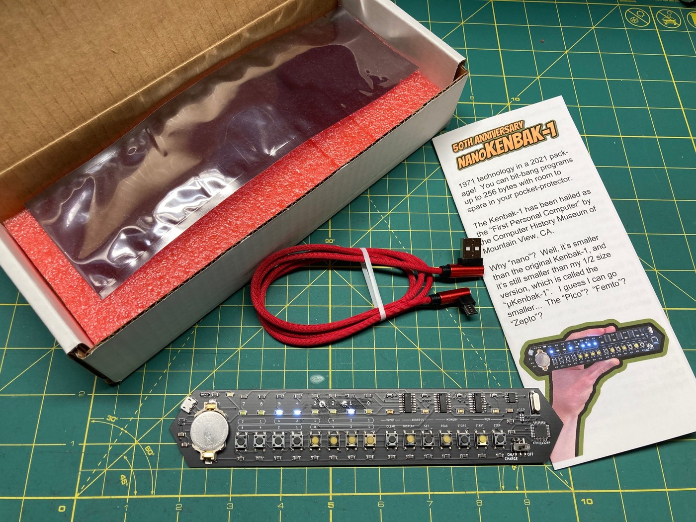
The Tindie listing’s contents: the “fully assembled and tested nanoKenbak-1”, an LIR2032 rechargeable battery, a USB cable and an instruction pamphlet (Tindie).
14.3 The Board, Part by Part
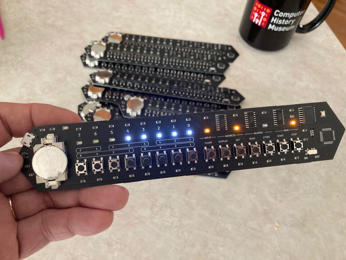
The board is black, pointed at both ends like the µKENBAK-1’s, with the front panel’s layout and legends printed in white silk screen. Reading the front from the left: the micro-USB socket, the charger chip and the LIR2032 in a clip-in holder at the pointed end; the DS3231 clock chip; the eight data lamps over their keys, labelled with the octal weights 2 1 / 4 2 1 / 4 2 1 above and 8 4 2 1 below, as on the original; then the control section, Input (Clear), Address (Display, Set), Memory (Read, Store) and Run (Start, Stop), with the three shift-register chips above their lamps; and at the right-hand point the ATmega328P, six unpopulated pads and the ON/OFF switch.
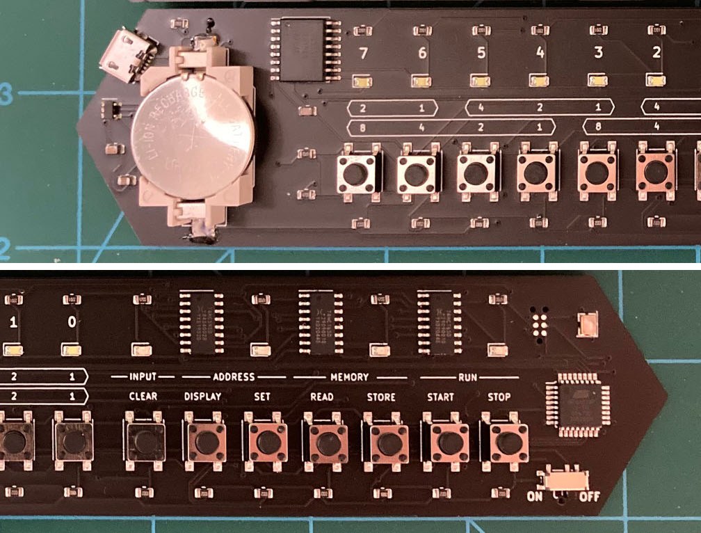
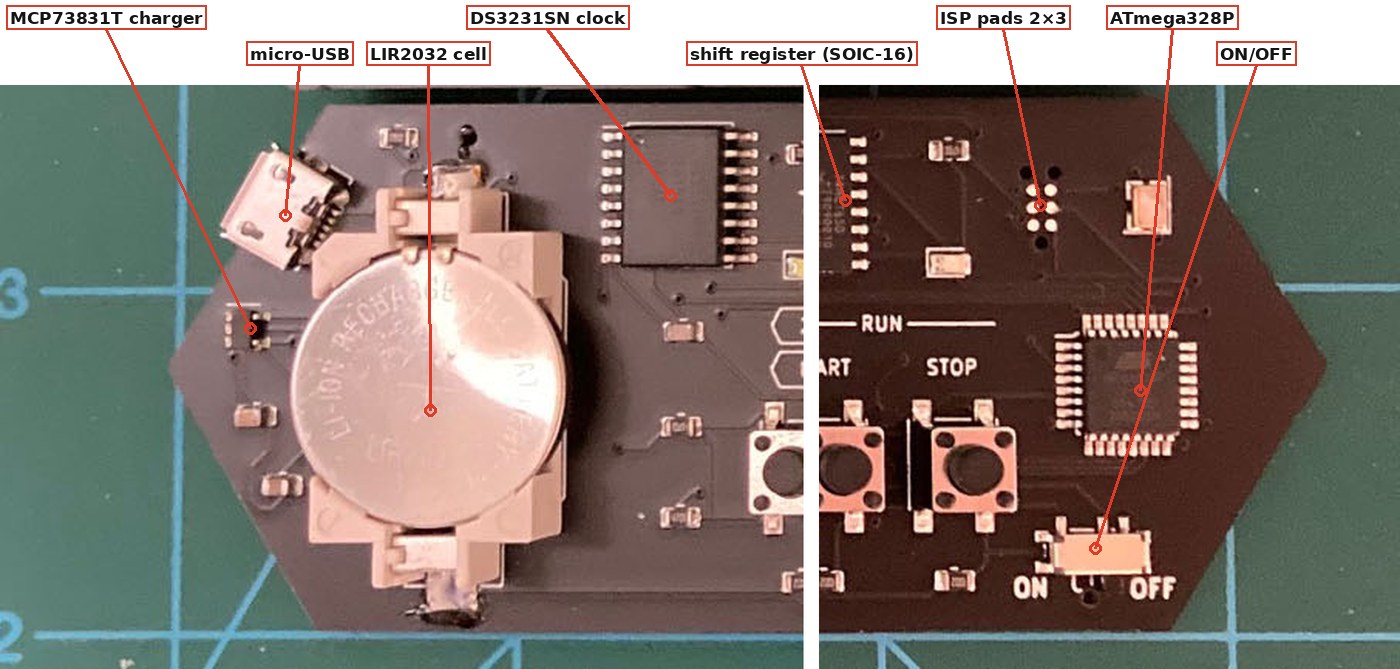
The back carries the instruction card in silk screen, so the board is its own manual: the list of built-in programs (Stop + 0 to Stop + 7), “Bit N + Stop: Set CPU Speed”, an eight-step procedure for setting the clock, the EEPROM save and load chords with the page sizes, and the credits “Software Copyright (c) 2021 Mark Wilson” and “PCB Copyright (c) 2021 Chris Davis”. At the right-hand end is the CR1616 coin cell, soldered in by its tabs, that keeps the clock running when the LIR2032 is flat or out.
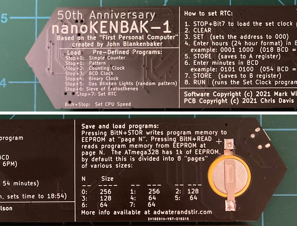
These photographs are the maker’s, from March 2021, of early boards. Units made since may differ in detail; a 2025 thread on the maker’s forum about a dead clock cell notes that an earlier nanoKENBAK-1’s design differs from newer units (ukenbak-1 group).
14.4 The Circuit
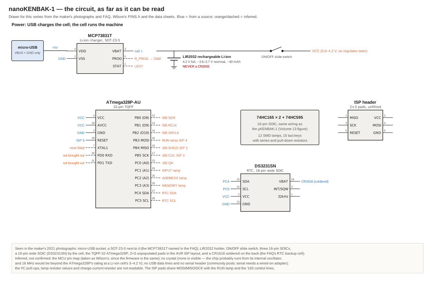
Because the firmware is the same as the µKENBAK-1’s, the processor must drive its lamps and read its keys on the same pins in the same way: a 74HC595 for the data lamps, two 74HC165s for the keys, four direct pins for the control lamps, and the clock on the I²C bus. Volume 13 draws that part out pin by pin. What the nanoKENBAK-1 changes is everything around it: the power, the clock chip, the oscillator and the way in.
14.4.1 Power: the cell runs the machine
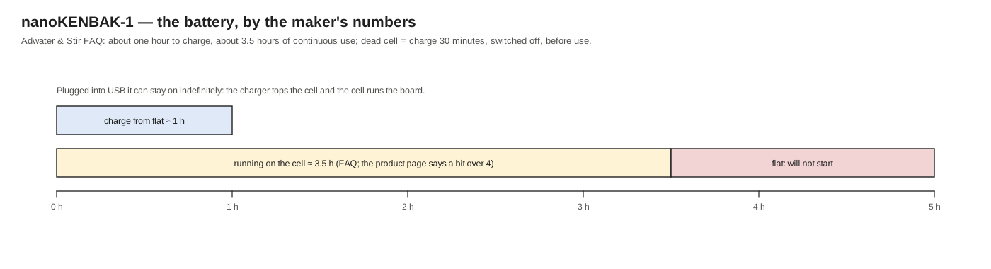
The maker’s FAQ is precise about the arrangement: “the device is not powered directly from USB — the USB charges the battery and the battery operates the device.” The micro-USB socket feeds a Microchip MCP73831T, a single-cell lithium-ion charge controller in a five-pin SOT-23 package, which charges the LIR2032 at constant current and then holds it at a constant 4.20 V until the current tapers off, and stops (Library copy; MCP73831 data sheet). The cell, through the ON/OFF switch, runs everything else. With USB connected, the charger keeps the cell topped up while the machine draws from it, which is why the FAQ says “you can leave it plugged into a USB power source continuously”.
Three consequences follow, all spelled out or implied in the FAQ:
- A flat cell means a dead machine, even on USB. “Your rechargeable battery must be present, and must have at least a small charge before you can turn on your nanoKenbak-1.” The cure is to switch it off, plug it in and wait about thirty minutes.
- No regulator is visible, so the supply rail is the cell’s own voltage, from 4.2 V when full down to about 3 V when flat. Every part on the board is happy across that range: the ATmega328P runs from 1.8 to 5.5 V, the 74HC parts from 2 to 6 V and the DS3231 from 2.3 to 5.5 V. The lamps are the parts that notice: their current, and so their brightness, falls with the cell’s voltage, the white lamps most of all, because a white LED needs close to 3 V before it lights at all.
- The micro-USB socket carries power only. Nothing on the board converts USB to serial, so the nanoKENBAK-1 cannot load or save programs over USB, and the serial chords of Volume 13 do nothing useful. When an owner asked on the maker’s forum in 2021 whether serial communication was possible, the maker’s answer was that one owner, Frank Prindle, had “added a serial connection to his nanoKenbak-1 … exposed a couple pins that he can connect to an FTDI->USB adapter”, and that the µKENBAK-1 kit was the easier route (ukenbak-1 group).
14.4.2 The clock: on the board, with its own cell
The µKENBAK-1 plugs in a clock module; the nanoKENBAK-1 has the DS3231SN chip itself, in its 16-pin wide package, beside the main cell. The DS3231 is a temperature-compensated clock with its crystal sealed inside the package, accurate to ±2 parts per million (about a minute a year) from 0 to 40 °C (Library copy; DS3231 data sheet). When its supply falls away it switches to its backup input, here the soldered CR1616 on the back, and keeps counting. The maker expects that cell to last “more than 10 years”.
14.4.3 The oscillator: probably the chip’s own
The µKENBAK-1 has a 16 MHz crystal. No crystal is visible anywhere on the nanoKENBAK-1 in the maker’s photographs, and there is a good reason for that: the ATmega328P’s data sheet allows 16 MHz only above about 3.8 V, and its safe speed at 3 V is about 11 MHz, so a board running from a lithium cell that sags to 3 V could not use the µKENBAK-1’s crystal within the chip’s rating (Library copy; ATmega328P data sheet, speed grades). The likeliest arrangement is that the chip runs from its internal 8 MHz oscillator, with the firmware built for that speed. This is an inference from the photographs and the data sheet, not a fact published by the maker, and it matters to anyone who reprograms the chip (below). The Tindie listing’s “(almost) 1khz” execution speed is in any case set mostly by the firmware’s delay, not by the clock.
14.4.4 The way in: six pads
At the processor end of the board are six plated holes in two rows of three, unpopulated: the standard layout of an AVR in-system programming (ISP) header, 1 MISO, 2 VCC, 3 SCK, 4 MOSI, 5 RESET, 6 GND. They are the only route to the processor’s flash memory. On an ATmega328P, the ISP lines are the same pins as PB3, PB4 and PB5, which Wilson’s pin map uses for the Run lamp, the shift registers’ load line and their clock. That causes no conflict during programming, because the processor’s pins are held in reset and the lines they drive are inputs to the other chips; it means only that the Run lamp and the key chips see some activity while the programmer works.
14.5 The Cell: LIR2032, Never CR2032
The nanoKENBAK-1’s main battery is an LIR2032: a lithium-ion coin cell, 20 mm across and 3.2 mm thick, rated about 3.6 to 3.7 V nominal and 40 to 45 mAh, charged to 4.2 V. It is exactly the size of the common CR2032, which is why the maker’s FAQ answers the question “I can just power this with a standard CR2032 battery, right?” with capitals:
ABSOLUTELY NOT! It will probably completely discharge a CR2032 in about 30 minutes, and if you connect to USB, you run the risk of an explosion. Seriously, don’t do it. Ever.
— Adwater & Stir, nanoKENBAK-1 FAQ
The reason is chemistry. A CR2032 is a primary lithium cell (lithium–manganese dioxide), 3 V, made to be used once at small currents; it cannot be recharged, and the charger in the nanoKENBAK-1 would try to push it to 4.2 V the moment USB was connected, which can make a primary lithium cell leak, vent or burst. Its high internal resistance also makes it a poor source for a load of several milliamps, which is the maker’s other point. The two cells look alike, and the only reliable difference is the marking: “LIR” (or “ML”, or “rechargeable”) on one, “CR” on the other.
Looking after the cell:
- Charge before first use, with the switch off: about an hour from flat.
- Do not leave it flat. A lithium-ion cell left fully discharged for weeks loses capacity and may not recover. If the nanoKENBAK-1 is to sit in a drawer, charge it first, switch it off, and top it up every few months.
- Leaving it plugged in is fine: the charger stops at 4.2 V and the cell runs the board.
- Expect the cell to wear out. Coin-size lithium-ion cells are rated for a few hundred cycles. When the running time falls well short of three hours, replace it.
- When replacing it, buy an LIR2032 from a known maker, check the marking, and fit it the right way round in the holder (positive face up, as printed). The cell clips in; nothing is soldered.
Two figures are worth having for comparison. A 40 mAh cell lasting 3.5 hours means the machine draws, on average, about 11 mA. A full charge in about an hour means the charger is set for roughly 40 mA, about one times the cell’s capacity per hour; LIR2032 data sheets differ on the maximum, some recommending half that for a standard charge, so a charge time of an hour is brisk but within what some makers allow. Both figures are simple arithmetic on the maker’s numbers, not measurements.
14.6 First Power-Up and Setting the Clock
- Charge it. Switch to OFF, connect the USB cable, and leave it about an hour (or thirty minutes if the cell came flat and only a first look is wanted).
- Switch on. The firmware shows a short lamp pattern, then waits with memory cleared to zero.
- Check every key and lamp with the original’s lamp test (Volume 6): each data key lights the lamp above it; Clear lights Input, Display lights Address, Read lights Memory and Start lights Run.
- Set the clock, by the procedure printed on the back: Stop + data key 7 loads the clock-setting program; Clear; Set (the address is now 000, register A); key the hour in BCD, 24-hour form, for example 0001 1000 for 18; Store (into A); key the minutes in BCD, for example 0101 0100 for 54; Store (into B); Start. The clock is set to 18:54 and runs from then on, on the CR1616 when the main cell is out.
- Run a clock: Stop + data key 2 (counting clock), 3 (BCD) or 4 (binary), then Start. Volume 13 explains how each one shows the time.
- Run Volume 9’s acceptance program to see which firmware fixes this board carries. Keyed by hand it is 26 bytes, counting P.
14.7 Programming It
With no serial port, every program goes in through the keys, exactly as on the 1971 machine. The procedure, the chords, the built-in programs, the EEPROM pages and the SysInfo call are all as on the µKENBAK-1 (Volume 13), with two practical differences: the data keys are small surface-mount switches, and the eight EEPROM pages matter more, because a program that has been keyed in by hand is worth keeping.
14.7.1 A first program to key
The seconds display from Volume 13 is short enough to key in a minute, and uses the board’s own clock. The lamp patterns below are the keys to press for each byte (● = pressed), from the series’ simulator:
Table 2 — The seconds display from Volume 13 is short enough to key in a minute, and uses the board's own clock. The lamp patterns below are the keys to press for each byte (● = pressed), from the series' simulator
| Step | Address | Byte | Keys (● = press) | Then |
|---|---|---|---|---|
| 1 | 003 | ○○ ○○○ ○●● | Set (address = 003) | |
| 2 | 003 | 004 | ○○ ○○○ ●○○ | Store (P = 004) |
| 3 | 004 | 023 | ○○ ○●○ ○●● | Store (LOAD A …) |
| 4 | 005 | 000 | ○○ ○○○ ○○○ | Store (… C=000: index 000, seconds) |
| 5 | 006 | 360 | ●● ●●○ ○○○ | Store (SYSX) |
| 6 | 007 | 134 | ○● ○●● ●○○ | Store (STORE B …) |
| 7 | 010 | 200 | ●○ ○○○ ○○○ | Store (… OUTPUT) |
| 8 | 011 | 344 | ●● ●○○ ●○○ | Store (JPD UNC …) |
| 9 | 012 | 004 | ○○ ○○○ ●○○ | Store (… 004); then Start |
Press Clear before keying each byte. The lamps then show the seconds as two BCD digits and change once a second: at 37 seconds, ○○ ●●○ ●●● (067). Data key 7 + Store saves it in EEPROM page 7 (64 bytes, ample), and holding Read + data key 7 at power-on makes the board start it every time it is switched on.
14.7.2 Longer programs
The programs of Volume 10 key in the same way; the longest, the primes and the guessing game, run to about seventy-five bytes each and take ten minutes or so with care. The keying patterns for every program are in their listings: each octal digit is one group of lamps, as printed on the board. For anything longer it pays to write the program first in the series’ simulator, kenbak_sim.py, run it there, and key it only once it works. Volume 13’s ukenbak_serial.py produces the octal bytes in order whichever machine they are for.
14.7.3 Adding a serial port
The firmware still contains the serial extensions, so a nanoKENBAK-1 with its processor’s serial pins brought out would load and save programs as the µKENBAK-1 does. Prindle’s modification is mentioned on the maker’s forum but its details are not published there. The pins are the ATmega328P’s RXD and TXD, pins 30 and 31 of the 32-pin package, on 0.8 mm centres, so the work is fine soldering on a board with no spare room. Any USB-to-serial adapter used with it must have 3.3 V logic: the board’s supply is the cell’s 3 to 4.2 V, and a 5 V adapter would drive the processor’s pins above its supply. This is an outline, not a tested procedure.
14.8 Reaching the Processor
The maker publishes no procedure for reprogramming the nanoKENBAK-1. A 2022 thread on the maker’s forum, “Kenbak-1 Program Counter Update”, concerned uploading a new sketch to a nanoKENBAK-1 or a newer µKENBAK-1, which shows that it has been done; the method is not quoted here because the thread could not be read in full. The ISP pads make it possible with ordinary tools, and the general method for an ATmega328P is well known. Three cautions come first, because each can lose the original firmware or harm the cell:
-
Save what is there before writing anything. The maker’s build may differ from Wilson’s published source (Volume 13 lists the known differences for the µKENBAK-1), and its oscillator setting is not published. With a programmer connected, read the flash, the EEPROM and the three fuse bytes and keep them:
avrdude -c usbasp -p m328p -B 10 \
  -U flash:r:nano-original.hex:i  -U eeprom:r:nano-eeprom.hex:i \
  -U lfuse:r:nano-lfuse.txt:h -U hfuse:r:nano-hfuse.txt:h -U efuse:r:nano-efuse.txt:h
If the chip’s lock bits are set, the flash reads back as meaningless data; in that case writing new firmware erases the original for good, and it is worth asking the maker for the image first.
-
Do not let the programmer power the board at 5 V. Many programmers can supply power on pin 2; on the nanoKENBAK-1 that pin is the cell’s rail, and 5 V there would be fed straight into a lithium-ion cell rated to 4.2 V. Run the board from its own cell, switched on, and set the programmer not to supply power. A programmer whose signals follow the target’s voltage (or one set to 3.3 V) keeps the logic levels within the processor’s rating.
-
Leave the fuses alone unless the original values have been read and the change is understood. In particular, do not burn the Arduino Uno’s fuses: they select an external crystal, and with no crystal on the board the processor would stop and could then be recovered only with a high-voltage programmer or an external clock.
A 2 × 3 pogo-pin adapter pressed onto the pads, or a 2 × 3 header held in them at a slight angle for the minute it takes, makes the connection without soldering; the slow programming clock (-B 10 above) suits the board’s slower oscillator. To build Wilson’s firmware for the board, the Arduino software needs a board definition that matches the chip’s real clock (for an internal 8 MHz oscillator, an ATmega328P “8 MHz internal” definition such as MiniCore’s), the DS3231 constants of Volume 13, and “Upload Using Programmer” rather than an ordinary upload, since there is no bootloader route.
14.9 Bill of Materials
The nanoKENBAK-1 is sold built, and the maker publishes no parts list. This list is for repairs: it names each part that can be identified from the photographs and the FAQ, and the part to buy to replace it. The tags are those of Volume 13. A printable version with tick boxes is at the end of this volume (Printable Bill of Materials).
Table 3 — Bill of Materials
| Qty | Where | Fitted | Buy now | Tag | Why |
|---|---|---|---|---|---|
| 1 | Main cell | LIR2032 (supplied) | LIR2032, 3.6–3.7 V, 40–45 mAh, from a known maker; positive face marked | Spec | The one part that wears out. Never a CR2032 (primary cell; see above) |
| 1 | Clock backup, back of board | CR1616, soldered by tabs | CR1616 with solder tabs | Same | A primary cell, correctly: the DS3231 does not charge its backup. Expected to last over ten years. Unsolder the old one before soldering the new; never heat the cell body |
| 1 | Charger | MCP73831T (FAQ), SOT-23-5 | MCP73831T-2ACI/OT or another -2 variant | Spec | The “-2” in the part number is the 4.20 V charge voltage the LIR2032 needs; other variants charge to other voltages. The fitted variant is not published: read its marking first |
| 1 | Processor | ATmega328P, TQFP-32 | ATmega328P-AU | Spec | A current part, but a new one is blank: it needs the firmware and the right fuses (see “Reaching the Processor”), so save the original’s image before any repair that replaces it |
| 1 | Real-time clock | DS3231SN, 16-pin wide SOIC | DS3231SN# | Same | The SN is the industrial-temperature version; the # marks the lead-free part |
| 2 | Key shift registers | 16-pin SOIC (from the photographs; with the firmware, 74HC165) | TI SN74HC165D | Spec | Identified by the firmware’s design, not read from the chips |
| 1 | Lamp shift register | 16-pin SOIC (74HC595 by the firmware) | TI SN74HC595D | Spec | As above |
| 8 + 4 | Lamps | white (data) and amber (control) surface-mount LEDs | Surface-mount LEDs of the same size and colour | Spec | Size not published; measure before ordering. An owner on the maker’s forum has suggested red data lamps instead of white, which would also stay brighter as the cell runs down (a red LED needs less voltage) |
| 15 | Keys | 6 mm surface-mount tactile switches (photographs) | 6 × 6 mm SMD tactile switch, four gull-wing legs, same height | Spec | Match the height to the original so that all fifteen feel alike |
| 1 | Power | ON/OFF slide switch, surface-mount | Miniature SPDT SMD slide switch of the same footprint | Spec | Measure the footprint before ordering |
| 1 | USB | micro-USB B receptacle, surface-mount | Micro-USB B SMD receptacle, matching footprint | Spec | The commonest failure on any micro-USB device; the joints of the shell’s tabs carry the strain |
| 1 | Cell holder | 20 mm coin-cell clip, beige | A 2032 holder of the same footprint | Spec | |
| — | Resistors, capacitors | surface-mount, values not readable | — | Spec | Not identifiable from photographs; a repair needs the board in hand |
| 1 | Programming | (not fitted) | 2 × 3 pogo-pin ISP adapter, or a 2 × 3, 2.54 mm header | Choice | Optional, for reaching the processor without soldering |
| 1 | Cable | USB cable (supplied) | Any micro-USB cable; it carries power only on this board | Same |
14.10 Faults and Fixes
Table 4 — Faults and Fixes
| Symptom | Likely cause | Fix |
|---|---|---|
| Will not switch on, even plugged into USB | The cell is flat; the board runs from the cell, not from USB | Switch off, charge thirty minutes, switch on |
| Runs much less than three hours on a full charge | The LIR2032 has worn out | Replace it (an LIR2032, never a CR2032) |
| Lamps dim, white ones first, as the session goes on | The cell’s voltage falling; there is no regulator | Normal; charge it |
| The time is lost whenever the main cell is flat or removed | The CR1616 backup cell is exhausted | Replace the soldered CR1616; then set the clock again |
| The clock drifts by minutes a month | Unusual for a DS3231 | Check the backup cell; set the clock |
| A key works only sometimes | A cracked joint on a surface-mount switch, often after the board has been flexed in a pocket | Reflow the switch’s four legs |
| No serial port appears on the computer | There is none; the micro-USB socket only charges | Key programs in; or see “Adding a serial port” |
| Stored programs gone after a firmware change | The EEPROM erased by the programmer (a chip erase does not keep EEPROM unless the fuse that preserves it is set) | Re-key and save; next time read the EEPROM out first |
| Programs from the manuals run as a blur | The emulator is far faster than the original | Data key 3 or 4 + Stop |
14.11 Three KENBAK-1s
With the full-size TTL machine of Volume 11 onward under way, the series will have three KENBAK-1s side by side, one from each family of Volume 8:
Table 5 — With the full-size TTL machine of Volume 11 onward under way, the series will have three KENBAK-1s side by side, one from each family of Volume 8
| Full-size TTL reproduction | µKENBAK-1 | nanoKENBAK-1 | |
|---|---|---|---|
| Logic | about 130 TTL chips, Blankenbaker’s circuit | ATmega328P emulation | ATmega328P emulation |
| Memory | two 1404A shift registers | processor RAM | processor RAM |
| Saving programs | none (as in 1971) | EEPROM, serial | EEPROM |
| Power | switching supply, +5, +12, −12 V | USB, 5 V | LIR2032, charged by USB |
| Real-time clock | none | DS3231 module | DS3231 chip |
| Speed | the original’s few hundred instructions a second | adjustable | adjustable |
| How it is made | a bare board, built part by part | a kit, an evening’s soldering | assembled by the maker |
All three run the same programs, keyed the same way, from the same 1971 manuals.
14.12 Printable Bill of Materials
The whole parts list above is also a printable PDF for the bench: nanoKENBAK-1 BOM (PDF). Each part has a row with tick boxes for ordered, in hand and fitted, the quantity and where it goes, the part number to buy, alternates, where to buy it, its tag and space for notes. The last page is an order log.
Next — Volume 15: Building a KENBAK-uino. Both of Adwater & Stir’s machines descend from one hand-wired box: Mark Wilson’s Arduino emulator of 2011. The next volume builds one from his published source and pin map — the circuit drawn in a comment, two boards squeezed together, five hundred solder joints — and compares his code with what the kits ship.
Comments (0)