KENBAK-1 · Volume 11
KENBAK-1 — Volume 11 — My Full-Size KENBAK-1 — Planning the Build
A chip-for-chip, full-size TTL reproduction: the board from Artem Kalinchuk, an engraved front panel from Front Panel Express, a case drawn from Bud Radio's 1965 Grand Prix drawings, and the decisions still open: which LEDs, how to socket the two memory chips, and the two aluminium side rails, which I am machining myself
11.1 About This Volume
Volume 9 built the half-scale µKENBAK-1, a microcontroller that emulates the KENBAK-1. This volume starts a different machine: a full-size reproduction with the original TTL logic, about 130 small-scale chips and two 1404A shift-register memories on a board laid out like Blankenbaker’s, behind a full-size front panel, in a copy of the blue Bud “Grand Prix” case. It is a build in progress. This first volume records what is ordered, what is still to decide, and what the case drawings ask of a home shop. Later volumes will follow the board, the panel, the case and the first program.
I have ordered the reproduction printed circuit board from Artem Kalinchuk and the front panel from Front Panel Express. I have quotes from PCBWay for the case: the sheet-metal top and bottom, and the two aluminium side rails that hold them together. The rails are the expensive part of the quote, so I am going to mill them myself, in my own shop (Volume 12).
11.2 The Plan in One Table
Table 1 — The Plan in One Table
| Part of the machine | Source | State on 2 November 2026 |
|---|---|---|
| Printed circuit board | Artem Kalinchuk (Volume 8) | ordered |
| Front panel, engraved | Front Panel Express, from my own design file | ordered |
| Rear panel | Front Panel Express, from my own design file | ordered |
| Case top and bottom | PCBWay, sheet metal, from the shared Bud drawings | quoted |
| Two side rails (Bud part 148) | machined in my own shop | to make |
| Chips, passives, switches, lamps, power supply | bought line by line | ordered |
| 1404A memories | second-hand | four bought: two to fit, two spares |
The Kalinchuk kit (listed at $650, without board or case) would have been the simple answer, because it contains the two 1404A shift registers, the one genuinely scarce part. It was sold out, so I bought only the board, and the rest comes line by line. I have now ordered all of it. The TTL chips, resistors and capacitors are ordinary catalogue items, from suppliers such as Tayda Electronics and Jameco. I bought four 1404As second-hand on eBay, two for the machine and two spares. Volume 8 sets out both routes.
11.3 What the Board Needs
The parts list below comes from the packing lists and part-placement sheet (Library copies: construction manual, placement guide) that Grant Stockly of Stockly Electronics issued with his KENBAK-1 reproduction kit in 2007. Both his board and Kalinchuk’s carry Blankenbaker’s circuit, so the count is the same, and these lists are the most complete count of a KENBAK-1 found for the series.
Table 2 — What the Board Needs
| Group | What | How many |
|---|---|---|
| Memory | 1404A 1,024-bit dynamic shift register, 8-pin metal can (not the 1401A) | 2 |
| Logic | 7400 quad NAND | 46 |
| 7410 triple 3-input NAND | 15 | |
| 7495 4-bit shift register | 13 | |
| 7474 dual D flip-flop; 7454 AND-OR-INVERT; 7430 8-input NAND | 10 each | |
| 7420 dual 4-input NAND | 9 | |
| 7442 BCD-to-decimal decoder | 4 | |
| 7404, 7486, 7416 | 3 each | |
| 7403 open-collector NAND | 2 | |
| 7408, 7451 | 1 each | |
| Resistors | 1 kΩ ×27, 3 kΩ ×4, 270 Ω ×4, 120 Ω ×4, 220 Ω ½ W ×2, 68 Ω ×2, 56 Ω 2 W ×1 | 44 |
| Capacitors | 0.1 µF ×25, electrolytics from 33 to 220 µF, two 6,800 pF and two 1,500 pF timing parts | about 40 |
| Semiconductors | 1N914 ×8, 1N4733 5.1 V zener, 2N4401 ×6, MPS3702 ×2 | 17 |
| Sockets | 14-pin ×126, 16-pin ×4, 8-pin machine-pin ×4 | 134 |
| Front panel | momentary keyswitches ×15 with caps (8 black, 7 white), 12 lamps (8 data, 4 control), a lock toggle, a power toggle | |
| Power | a triple-output supply, +5 V, +12 V and −12 V | 1 |
Two details from the Stockly manual change how the board is built. The first is the memories, covered in the next section. The second is the logic family: the kenbak.com builders’ guide used standard 74-series chips and was unsure whether low-power Schottky parts would work in this design, so standard 7400-series parts are the safe choice. The 7454 is a particular trap, because the 74LS54 is not the same gate arrangement.
The family matters for anyone tempted by modern parts. A 74HC00 is not a stronger 7400: it is CMOS, with different input thresholds and different behaviour from unconnected inputs, and the 7416 open-collector driver has no HC equivalent at all.
The supply is the one part that has to be modern. The original’s linear supply, with two transformers and a heat sink, wasted most of its power as heat; Stockly and Kalinchuk both use a switching supply instead. The kenbak.com guide measured a working board at about 2.3–2.5 A on the 5 V rail and under 0.3 A on −12 V.
11.4 Socketing the Memories
On an original KENBAK-1 the two 1404A cans were soldered straight into the board. A reproduction can do better, because a part that is now fifty years old should come out without heat. There are two ways to do it.
- A carrier (Stockly’s method). The can’s eight leads, which leave it on a 0.200 in circle, are bent outward into two rows and soldered into an 8-pin machine-pin DIP socket. That socket then plugs into a second machine-pin socket on the board. Can pin 1 goes to socket pin 1 and so on round, because the pins run the same way on the can as on a DIP package, and the can’s tab points to the notched end, where pins 1 and 8 sit.
- A round socket. Sockets made for 8-lead metal cans are still in production: Mill-Max’s series 917 has an 8-pin version on the same 0.200 in circle (917-43-108-41-005000 for through-hole mounting). The leads stay straight and nothing is soldered to the can. It fits directly only where the board has a round 8-hole footprint. On a board with a DIP-8 footprint it needs a small adapter board, with the round socket on top and two rows of header pins beneath.
The carrier sits about 18 mm above the board, the round socket about 13 mm and the round socket on an adapter about 20 mm, all far below the case lid. A push-on TO-5 heat sink fits all three. Mill-Max rates the through-hole socket for leads 0.018 to 0.025 in thick, so the 1404A’s leads need measuring first; the surface-mount version takes leads down to 0.015 in.
I plan to build both and keep whichever works better, using the two spare 1404As for the trials. Which one is possible depends on the footprint of the board’s two memory positions, DIP-8 or round, and that is the first thing to check when the board arrives.
11.5 The Case: Bud Radio’s Grand Prix
The KENBAK-1 lived in a stock enclosure, Bud Radio’s MD-1 “Grand Prix”, drawn on 8 March 1965 and long out of production. Bud gave Chris Davis of Adwater & Stir the original drawings (Library copies: case set, rail set) when he went looking for a case for his full-size replica, and Davis converted them to millimetres and shared them, with CAD files, on PCBWay’s community site (Volume 8). Those files are what the PCBWay quote is built from.
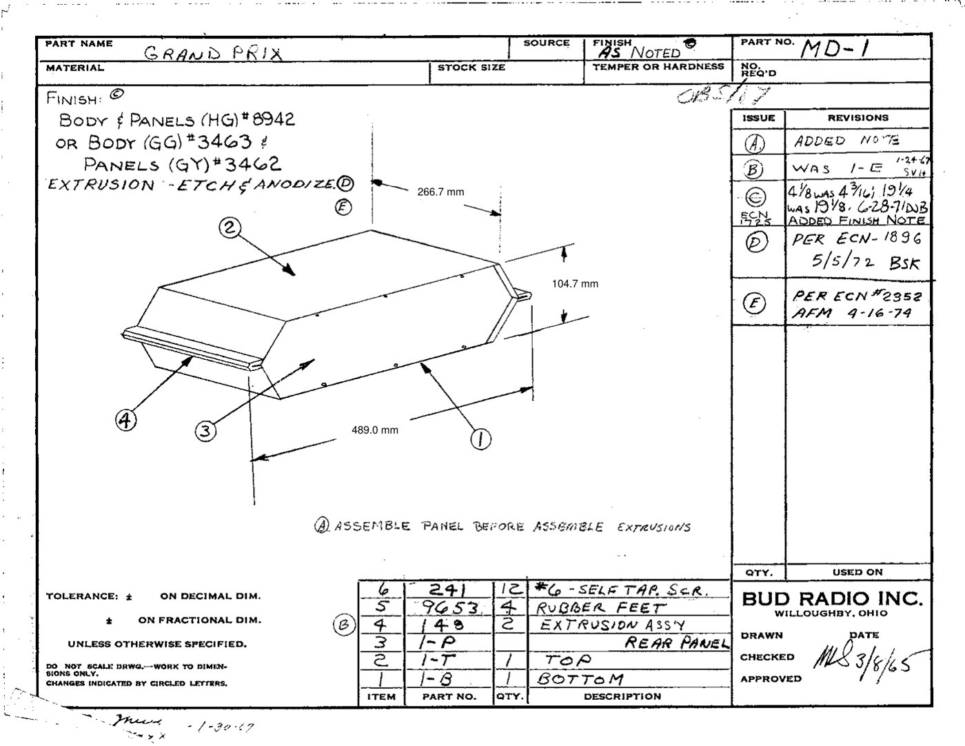
The drawing shows how the case goes together. The top and bottom are folded sheet steel, a clamshell whose long edges meet along each side. Each side is then capped by a 266.7 mm aluminium extrusion, Bud part 148, which slides over the meeting edges and holds the two halves together; set screws through the extrusion clamp them. A note on the drawing says to fit the panel before the extrusions. The original finish was a painted body and panels, and the extrusions were etched and clear-anodised.
11.6 The Side Rails
The rail is the most demanding part of the case to make, which is why it dominates the quote. Bud’s cross-section drawing gives the profile.
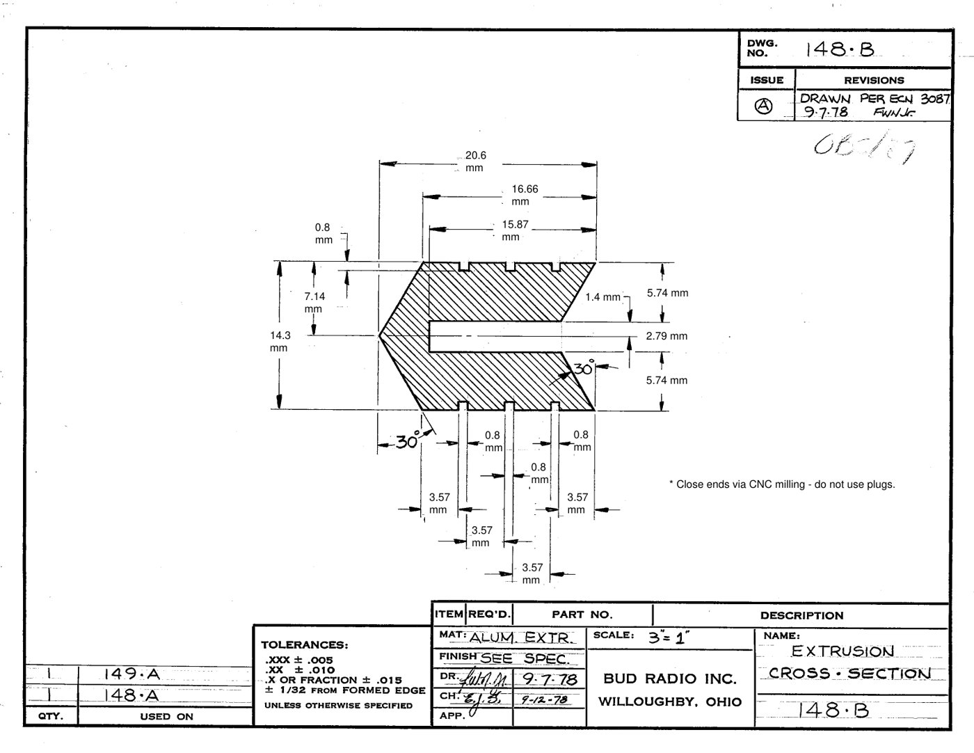
Table 3 — The Side Rails
| Feature | Size |
|---|---|
| Section | 20.6 mm wide × 14.3 mm high |
| Length | 266.7 mm (cut from 10½ in stock) |
| Outer face | a point formed by two 30° faces |
| Slot | 2.79 mm wide, centred, between 5.74 mm walls |
| Grooves | three 0.8 mm grooves on each flat face, spaced 3.57 mm |
| Holes | two 3.2 mm through-holes, 23.85 mm from each end (219.0 mm apart) |
| Ends | closed by machining, not plugged |
Bud made it as an extrusion, so the slot and the grooves cost nothing. Cut from solid bar, every feature is a separate machining operation, which is why a CNC job shop charges so much for two of them. Bar stock of 6061 aluminium, 7/8 × 5/8 in, leaves enough on every face to finish to 20.6 × 14.3 mm.
Two machines in my shop can make the rail:
- The mini mill. My HiTorque 3990 has 300 mm of X travel, enough to cut the full 266.7 mm in one setting. The long slot suits a slitting saw (a 7/64 in saw cuts 2.78 mm) and the grooves a 1/32 in saw; the 30° faces need a chamfer cutter or an angle vice, because the mill’s column does not tilt.
- The CNC router. My Shapeoko 3 XXL has more than enough bed for the rail, and a V-bit or chamfer tool can cut the 30° faces in one pass, with the bar flipped in a fixture for the second side. The deep, narrow slot is the hard feature for a router: a long-reach end mill under 2.8 mm is slender for aluminium, so the slot may be best finished on the mill.
11.7 The Case Files
The models behind the PCBWay quote can be downloaded here: KENBAK-1 case CAD files (zip, 1 MB). They are Chris Davis’s files from his PCBWay community project (KENBAK-1 Case), renamed without spaces and otherwise unchanged, with a README and checksums.
What is in the zip
Table 4 — What is in the zip
| File | Part | Size (mm) |
|---|---|---|
kenbak-1-case-top-bottom.iges | one case half; the same model is used for the top and the bottom | 479.1 × 52.2 × 266.9 |
kenbak-1-case-side-rail.iges | side rail, Bud 148 (two needed) | 20.6 × 14.3 × 266.7 |
kenbak-1-case-front-panel.iges | front panel | 454.3 × 100.0 × 1.2 |
kenbak-1-case-rear-panel-modified.iges | rear panel, modified | 448.9 × 100.0 × 1.2 |
kenbak-1-front-panel-artwork.svg / .ai | front-panel legend artwork | — |
The drawings that go with them are in the Library: the case set (Library copy) and the rail set (Library copy).
One warning before sending them to a fabricator. Three of the four models (the case half, the rail and the front panel) are surface models, not solids. Checked in FreeCAD, each is a set of trimmed surfaces with small gaps around the screw holes and along some edges, and none of them forms a closed solid. Most CAD programs open them and they look right on screen, but a quoting or CAM system that needs a solid can report the file as unreadable. PCBWay’s system read the rail and the front panel, but not the case half. Stitching the surfaces into a solid (in Fusion, Surface › Stitch) and exporting STEP gives a file such a system can read. The rear panel is already a solid.
11.8 Still to Decide
- Lamps: the original’s 5 V incandescent lamps in white and yellow lenses, or LEDs, which both current kits use for reliability. I am leaning towards LEDs, but which ones is still open.
- Rails: I am making them myself; which machine, the mill or the router, is still open (Volume 12).
- Memory sockets: carrier or round socket, once the board is here.
Next — Volume 12: My Full-Size KENBAK-1 — The Board, the Memories and the Bill of Materials. The reproduction board gone over close up — where the two 1404A memories go and how they are socketed, the 1971 schematic, a line-by-line parts list with today’s substitutes for the obsolete parts, how to bring the board up, and how I am milling the side rails.
Comments (0)