Antikythera · Volume 6
Antikythera — Volume 6 — Gears from the Greeks — The Gear Train
From a lost crank to five back-dial pointers and a Moon that speeds up and slows down: every surviving tooth count, every ratio worked out, and what the CT scans changed
6.1 About This Volume
Volume 5 set out the astronomy. This volume follows it into the bronze: the input, the main wheel, and the four trains that turn the numbers of the sky into the motions of pointers. Each train is traced gear by gear, each ratio is multiplied out and checked, and the resulting period is compared with the astronomical value it was meant to reproduce. The tooth counts are the heart of the matter, so the volume is careful about where they come from and how sure they are.
The reference model is the one published by the Antikythera Mechanism Research Project in 2006 and revised in 2008 — T. Freeth et al., Nature 444 (2006) 587–591, Fig. 5 (N06, doi:10.1038/nature05357), and T. Freeth, A. Jones, J. M. Steele and Y. Bitsakis, Nature 454 (2008) 614–617 and Supplementary Notes (N08, supplementary PDF). Every tooth count printed below has been checked against N06’s Figure 5 or the N08 notes, and each is marked as surviving or reconstructed. The ratio checks were done with exact fractions. Later work, chiefly T. Freeth and A. Jones, “The Cosmos in the Antikythera Mechanism”, ISAW Papers 4 (2012) (FJ12, online) and the 2021 Scientific Reports model (SR21, doi:10.1038/s41598-021-84310-w), adds lost gearing in front of the main wheel for the planets; that is Volume 10’s subject. The gearing described here is the gearing that survives, plus the handful of gears that must have existed to connect it.
6.2 How the Gears Are Known
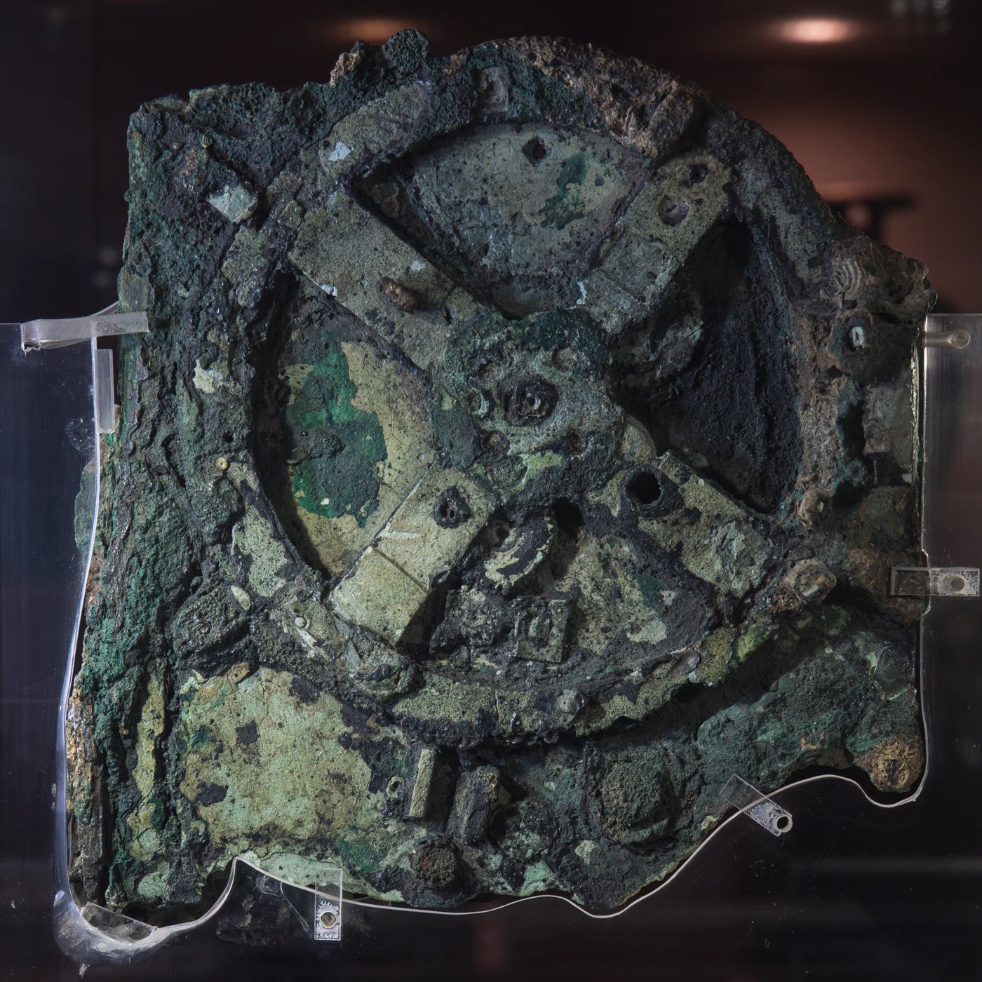
At least 30 gears survive: “27 hand-cut bronze gears are in fragment A and one gear in each of fragments B, C and D” (N06). Almost none can be seen whole. They are corroded into the fragments, stacked behind one another, often broken, sometimes displaced from their axes. Price in the 1970s worked from flat radiographs taken by Charalambos Karakalos; Michael Wright and Allan Bromley in the 1990s used linear tomography; the decisive data came from the microfocus X-ray computed tomography (CT) carried out in Athens in 2005 by X-Tek Systems for the AMRP (Volume 4).
From the CT, the team measured the angle of every surviving tooth tip about a nominal centre and fitted a model of regularly spaced teeth, varying the count (and, where the centre was unclear, the centre) to minimise the scatter. In N06’s words: “In a few cases all teeth can be seen, but many gears are incomplete. Counts are established by fitting models with regularly spaced teeth and minimising the r.m.s. deviation from the measurements.” Each count is therefore a statistical best fit. For most gears the fit is unambiguous; for a few there are alternatives, and the model chosen is the one whose ratios make astronomical sense. That is circular only in a mild way: a proposed count that fits the teeth and also produces an exact astronomical period is far more likely than chance.
6.2.1 The naming system
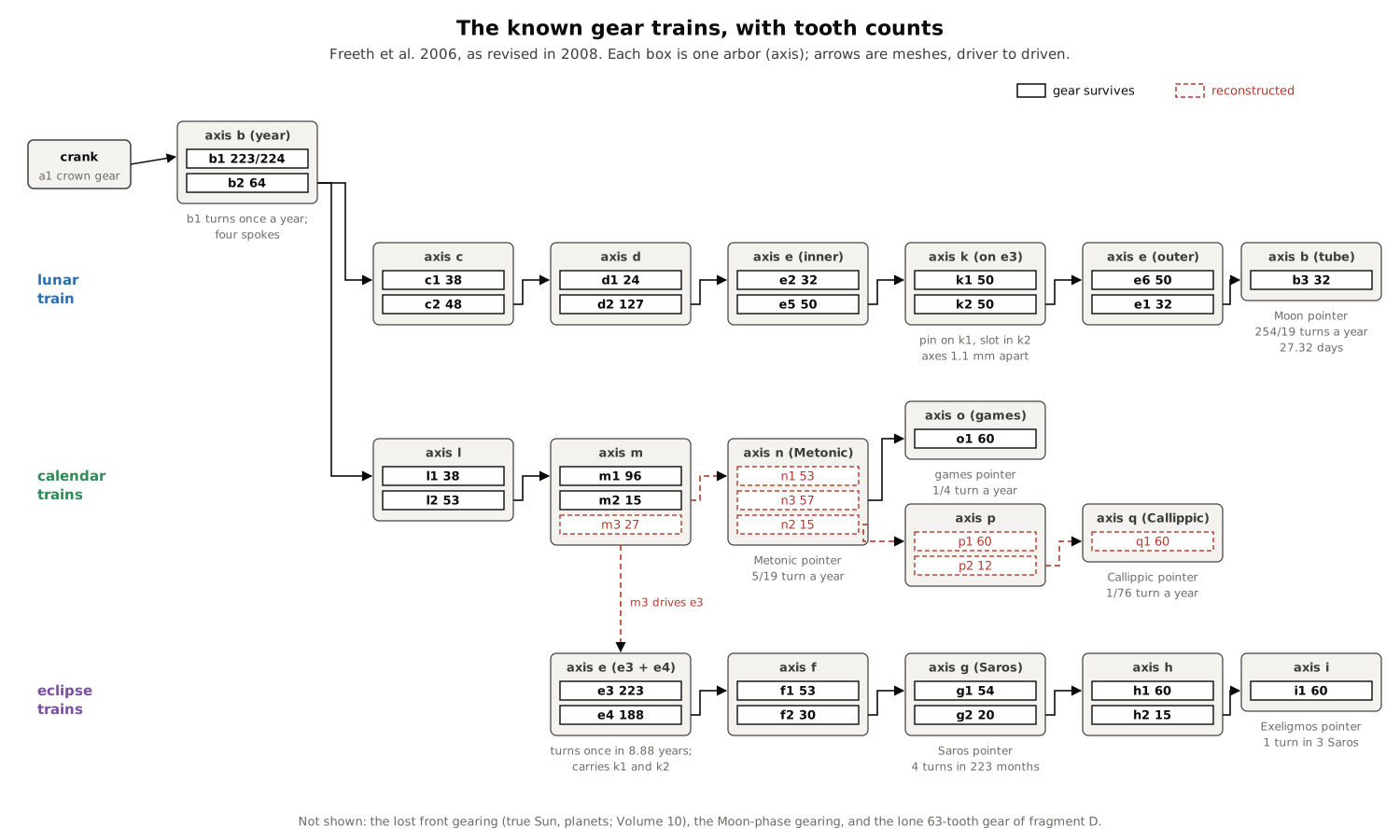
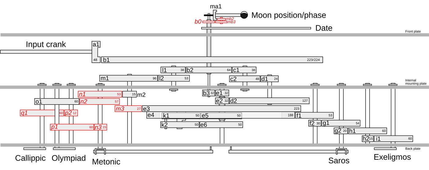
N06 introduced a systematic nomenclature. Each gear takes the lower-case letter of its axis, and a number that increases with distance from the front of the mechanism. So b1, b2 and b3 all turn on axis b, b1 being the frontmost. Hypothetical gears — ones that do not survive but that the model needs — are printed in italics in N06 and drawn in red in the figure below. Two later renamings must be watched. N08 reassigned the gear o1 from a Callippic train to the newly identified games dial, and the labels n2 and n3 are swapped between N08 and some later diagrams, including FJ12’s and the Wikipedia table derived from it. The ratios are identical either way; this volume follows N08, in which n3 is the 57-tooth gear that drives the games dial.
6.3 Teeth Without Involutes
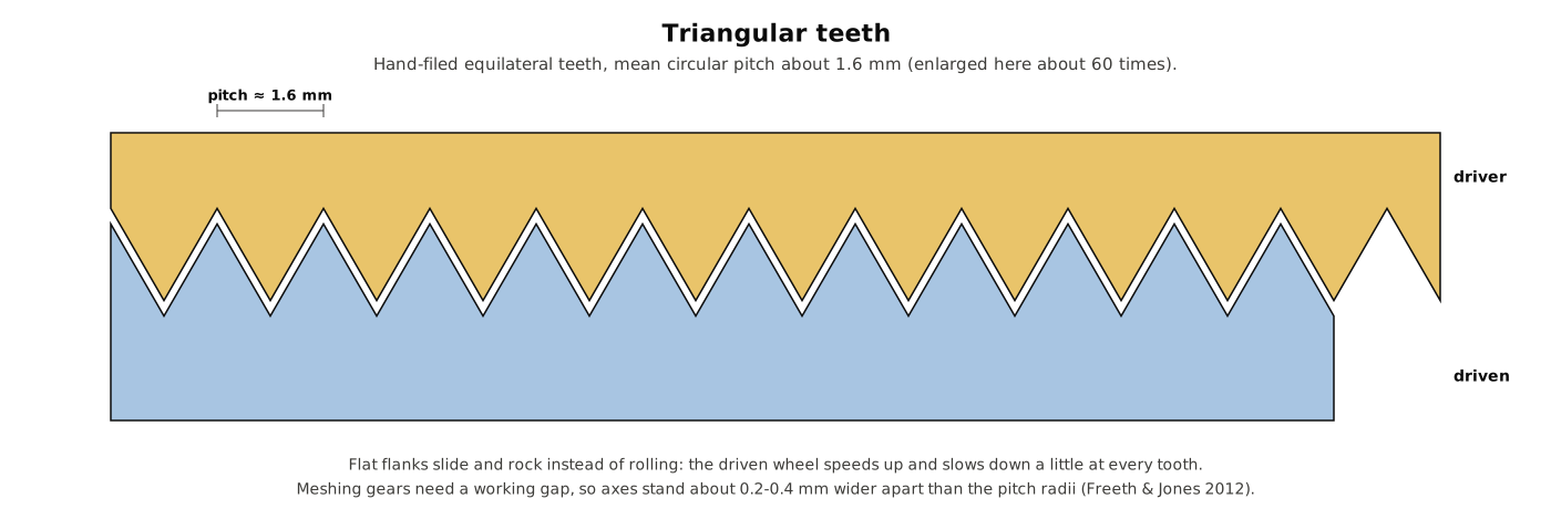
The gears are cut from bronze sheet about 1.4 mm thick, with teeth that are, in profile, roughly equilateral triangles. Wikipedia’s summary of the AMRP measurements gives a mean circular pitch of about 1.6 mm, a mean wheel thickness of 1.4 mm and a typical air gap between gears of 1.2 mm (Wikipedia, “Antikythera mechanism”); N08 describes the teeth as “about 1.5 mm long”. FJ12, modelling the gears, assumes that meshing axes stand about 0.2–0.4 mm further apart than the sum of the pitch radii, “since triangular-toothed gears cannot mesh too closely”.
Triangular teeth do not roll on one another as modern involute teeth do. They slide and rock, so that the driven wheel speeds up and slows down slightly as each tooth passes. The divisions are not perfectly even either: FJ12 notes that “the unevenness of some of the divisions of some of the gear teeth suggests that a dividing engine was not used for the gears and that they were hand-cut with a file”. The marking-out was probably done with dividers and repeated bisection where the count allowed it, and by stepping-off where it did not — a 64-tooth wheel can be laid out by halving six times; a 53- or 127-tooth wheel cannot.
How much error this introduced is a live question. Michael Edmunds estimated the tooth-placement and centring errors from the CT and concluded that the cumulative slop in the trains would have been large (“An Initial Assessment of the Accuracy of the Gear Trains in the Antikythera Mechanism”, Journal for the History of Astronomy 42 (2011) 307–320, ORCA). In 2025 Esteban Szigety and Gustavo Arenas modelled triangular teeth explicitly and found that the tooth form itself costs almost nothing, but that errors at Edmunds’s levels would jam the trains — so either the real errors were smaller than estimated, or the machine never ran smoothly (arXiv:2504.00327). Volume 11 weighs that argument. For this volume what matters is that the ratios are exact: whatever the slop within a turn, a train with the right tooth counts keeps the right average rate for ever.
6.4 Input: The Crank and the Year Wheel
The mechanism was driven from its right-hand side. The handle is lost; what survives is the keyway for the input on a crown gear, a1, whose teeth stand at right angles to its face and mesh with the rim of the great four-spoked wheel b1. FJ12 describes the input crown gear in the CT and the pillars on b1 that stand close to it. Turning the handle turned b1, and b1 turned once per year.
b1 is the largest gear, about 13 cm across. Its tooth count is not certain: Price counted 223, the AMRP’s Figure 5 labels it 224, and some later summaries give one or the other. The question matters less than it might, because b1 is an input wheel: it is the year, by definition, and nothing downstream depends on its count except the gearing ratio from the crank. A figure of about 78 days per turn of the crank is often quoted; that depends on an assumed count for the crown gear, which is not securely known (some reconstructions give it 48 teeth, and 224/48 turns of the crank per year gives one turn per 78.3 days). On b1’s face are the remains of pillars and fittings that show it once carried more gearing in front of it — the lost planetary and solar mechanisms of Volume 10.
On the same axis, behind b1 and fixed to it, is b2 (64 teeth). Everything else is driven from b2. Sixty-four is the friendliest possible count for hand division (2⁶), and it drives two trains at once: the lunar train through c1, and the calendar and eclipse trains through l1.
The date pointer and the mean-Sun pointer on the front dial are carried round by b1’s axis directly: one turn a year.
6.5 The Lunar Train: 254/19
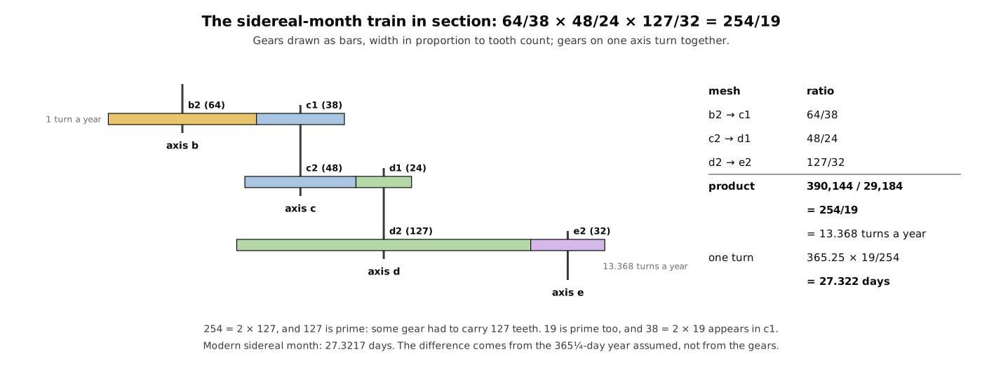
The Moon pointer must turn 254 times while b1 turns 19 times (Volume 5). That ratio, 13.368…, is too large for a single pair of gears of sensible size, and 254 = 2 × 127 and 19 are both awkward. The designer split it into three meshes:
Table 1 — The Moon pointer must turn 254 times while b1 turns 19 times (Volume 5). That ratio, 13.368…, is too large for a single pair of gears of sensible size, and 254 = 2 × 127 and 19 are both awkward. The designer split it into three meshes
| Mesh | Driver | Driven | Ratio (driven turns per driver turn) | Status |
|---|---|---|---|---|
| 1 | b2, 64 | c1, 38 | 64/38 | both survive |
| 2 | c2, 48 | d1, 24 | 48/24 | both survive |
| 3 | d2, 127 | e2, 32 | 127/32 | both survive |
Multiplying the three: (64 × 48 × 127) / (38 × 24 × 32) = 390,144 / 29,184 = 254/19 exactly. To see the cancellation: 64 × 48 / (38 × 24) = 3,072 / 912 = 64/19; then 64/19 × 127/32 = 2 × 127 / 19 = 254/19.
So e2 turns 254/19 = 13.3684 times a year. With a year of 365¼ days, one turn takes 365.25 × 19 / 254 = 27.322 days, against a modern sidereal month of 27.3217 days. The error, about 0.0001 days a month, comes almost entirely from the 365¼-day year, not from the gears: the 254/19 relation itself is good to about two hours in 19 years.
6.5.1 Why a 127-tooth wheel
The sidereal ratio contains the prime 127, and a prime factor in a ratio must appear on some gear: it cannot be built up from smaller wheels. A 254-tooth wheel would have been larger than b1. Halving it to 127 and putting the 2 elsewhere (64/32 contains it) gives a wheel of a size that fits, at the cost of a count that cannot be laid out by bisection. The 19 is placed in c1 (38 = 2 × 19). In this train, as in every train of the mechanism, the tooth counts are the prime factors of astronomical relations, distributed so that no wheel is too big or too small. That is the “economy of design” which N06 and N08 praise again and again.
6.5.2 From the mean Moon to the true Moon
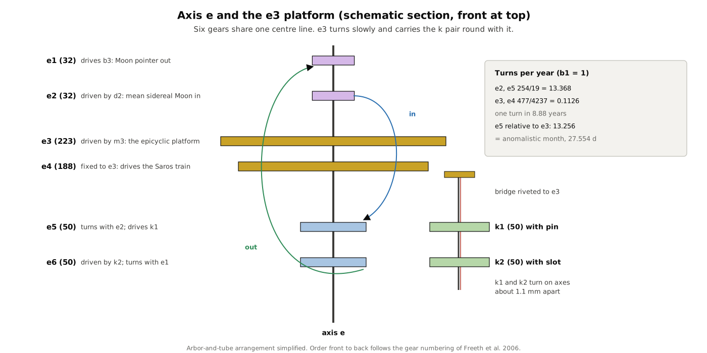
If e2 drove the Moon pointer directly, the pointer would move uniformly: a mean Moon. It does not. On the same arbor as e2, at the back of the mechanism, is e5 (50 teeth), and here the train passes through the most ingenious part of the machine:
Table 2 — If e2 drove the Moon pointer directly, the pointer would move uniformly: a mean Moon. It does not. On the same arbor as e2, at the back of the mechanism, is e5 (50 teeth), and here the train passes through the most ingenious part of the machine
| Mesh | Driver | Driven | Ratio | Status |
|---|---|---|---|---|
| 4 | e5, 50 | k1, 50 | 1 | both survive |
| 5 | k1 → k2 by pin and slot | 1 on average | both survive | |
| 6 | k2, 50 | e6, 50 | 1 | both survive |
| 7 | e1, 32 | b3, 32 | 1 | both survive |
All four k and e gears in the loop have 50 teeth, so the average ratio round the loop is exactly 1: the Moon pointer still makes 254 turns in 19 years. But k1 and k2 are not on one axis. They turn on axes about 1.1 mm apart, and k1 drives k2 not by teeth but by a pin on k1’s face that runs in a radial slot in k2. Because the pin’s distance from k2’s centre changes as they turn, k2 runs alternately ahead of and behind k1 — the variable motion that represents the Moon’s anomaly. Volume 7 works through the geometry; the essential numbers are N06’s: axis offset about 1.1 mm, pin 9.6 mm from k1’s centre, maximum lead or lag about 6.5°.
From e6 the motion goes forward to e1 at the front of axis e, then across to b3 (32 teeth), a tube on axis b that carries the Moon pointer over the front dial. e1 and b3 have equal counts, so this last pair simply transfers the motion and reverses its direction to match the Sun’s.
6.6 The Great Wheel e3: An Epicyclic Table
The k gears are not mounted on the frame. They ride on e3, a large wheel of 223 teeth, which turns slowly on axis e. As e3 turns, it carries the whole pin-and-slot assembly round with it. This is the feature that turned the AMRP’s reading of the machine.
If k1 and k2 were on fixed axes, the variation they produce would repeat once per turn of k1 — once per sidereal month, since k1 is driven from e5 at the sidereal rate. But the Moon’s speed varies over the anomalistic month, which is about 0.23 days longer, because the line of apsides moves forward. Mounting k1 and k2 on a platform that itself turns at the rate of the line of apsides subtracts that rotation: relative to e3, k1 turns at the sidereal rate minus e3’s rate, which is the anomalistic rate. N06 describes it as “the remarkable purpose of mounting the pin-and-slot mechanism on the gear e3”, which is “to change the period of variation from sidereal month … to anomalistic month — by carrying the gears epicyclically at a rate that is the difference between the rates of the sidereal and anomalistic months, that is, at the rate of rotation of about 9 years of the Moon’s apogee”.
This is epicyclic gearing — gears carried on another gear — and it is the earliest known. The output then has to get off the moving platform and back to a fixed axis, which is why the motion returns from k2 to e6, coaxial with e3, and thence through e3’s centre to e1.
6.6.1 How fast e3 must turn, and why 53
The line of apsides advances at the difference between the sidereal and anomalistic rates. The designer had no modern month lengths; he had the Metonic and Saros relations. From them:
- sidereal months per year = 254/19
- anomalistic months per year = 239 anomalistic months per Saros × (Saros per year). A Saros is 223 synodic months, and there are 235/19 synodic months per year, so there are 235/(19 × 223) Saros per year, and 239 × 235 / (19 × 223) anomalistic months per year.
- difference = 254/19 − 239 × 235/(19 × 223) = (254 × 223 − 239 × 235) / (19 × 223) = (56,642 − 56,165) / 4,237 = 477/4,237 turns per year.
And 477 = 9 × 53. That is FJ12’s formula for the rotation of the line of apsides, “(9 × 53)/(19 × 223)”, and it is why the mechanism has two gears of 53 teeth. N06 makes the point emphatically: “Gears with 53 teeth are awkward to divide. So it may seem surprising that the gearing includes two such gears (f1, l2) … But the gearing has been specifically designed so that the ‘epicyclic table’ e3 turns at the rate of rotation of the Moon’s apogee — the factor 53 being derived from the calculation of this rotation from the Metonic and Saros cycles … The establishment of the 53-tooth count of these gears is powerful confirmation of our proposed model of Hipparchos’ lunar theory.”
The train to e3 is:
Table 3 — The train to e3 is
| Mesh | Driver | Driven | Ratio | Status |
|---|---|---|---|---|
| 1 | b2, 64 | l1, 38 | 64/38 | both survive |
| 2 | l2, 53 | m1, 96 | 53/96 | both survive |
| 3 | m3, 27 | e3, 223 | 27/223 | m3 reconstructed; e3 survives |
Product: 64/38 × 53/96 × 27/223. The first two fractions give 64 × 53 / (38 × 96) = 53/57; times 27/223 gives 53 × 27 / (57 × 223) = 9 × 53 / (19 × 223) = 477/4,237 turns per year — exactly the required rate. One turn of e3 takes 4,237/477 = 8.8826 years (3,244.4 days), against a modern period for the Moon’s apsidal rotation of about 8.85 years. Relative to e3, the k gears then turn 254/19 − 477/4,237 = 56,165/4,237 times a year, one turn every 27.554 days — the anomalistic month, which the modern value of 27.5546 days matches to within a minute.
Gear m3 does not survive, but N06 notes that its “proposed shaft is clearly broken off in the CT”, and a 27-tooth wheel there is the only simple choice that makes the ratio come out. It is the one gear N06 had to add beyond those proposed by earlier researchers for the calendar trains.
6.6.2 Two jobs for one wheel
N06 remarks that e3 “has found no use in previous models”: its 223 teeth had meshed with nothing in any earlier reconstruction. In the AMRP model it does two things at once. Its rotation, 477/4,237 turns a year, is the apsidal rate that the lunar anomaly needs. And fixed to it is e4 (188 teeth), which drives the eclipse dials. One rate serves both because the Saros train can be built on top of it: the 223 in e3 and the 53 in l2 are exactly the factors the Saros dial needs to cancel out, as the next section shows.
6.7 The Calendar Trains: Metonic, Games and Callippic
From b2 the calendar train shares its first two meshes with the e3 train and then branches:
Table 4 — From b2 the calendar train shares its first two meshes with the e3 train and then branches
| Mesh | Driver | Driven | Ratio | Status |
|---|---|---|---|---|
| 1 | b2, 64 | l1, 38 | 64/38 | both survive |
| 2 | l2, 53 | m1, 96 | 53/96 | both survive |
| 3 | m2, 15 | n1, 53 | 15/53 | m2 survives; n1 reconstructed |
Product: 64/38 × 53/96 × 15/53 = 53/57 × 15/53 = 15/57 = 5/19 turns per year. The 53s cancel. The Metonic pointer on axis n therefore makes 5 turns in 19 years — one turn every 1,387.95 days — and in 19 years covers the five turns of the 235-month spiral on the upper back dial (Volume 8). The same check was published by Diomidis Spinellis in 2008: “the sequence b2-l1-l2-m1-m2-n1 calculates this ratio: 64/38 × 53/96 × 15/53 = 960/3648 = 5/19” (D. Spinellis, “The Antikythera Mechanism: A Computer Science Perspective”, IEEE Computer 41(5), 2008).
The gears on axis n are lost. n1, and the earlier proposal of n2, p1 and p2, go back to Michael Wright’s models; N06 agrees “with the assumption of four missing gears (n1, n2, p1, p2) to drive the Metonic and Callippic dials”.
6.7.1 The games dial: 57/60
Inside the Metonic spiral is a small dial divided into four years. Underneath it, in fragment B, the CT shows the partial remains of a gear, o1, which “statistics establish beyond reasonable doubt … had 60 teeth” (N08, Suppl. 3.6). N08 proposed that a single further gear on axis n drives it: n3, 57 teeth.
- 5/19 × 57/60 = 285/1,140 = 1/4 turn per year
The games pointer therefore goes round once in four years. N08 checks the geometry as well as the ratio: a 57-tooth gear at o1’s pitch would have a pitch radius of 11.9 mm, o1’s is estimated at 12.5 mm, and the distance between axes n and o is 24.4 mm — “exactly the sum”. The reversal of direction at this mesh also explains why the games dial is the only pointer known to turn anticlockwise: the designer chose the simplest gearing and inscribed the dial to suit it.
6.7.2 The Callippic train: 1/76
The 76-year Callippic cycle (Volume 5) is named in the back-cover inscription, and the subsidiary dial once thought to show it is now the games dial. N08 therefore proposes a second subsidiary dial, symmetrically placed, driven by “the mirror image of the gearing originally proposed” by Wright:
Table 5 — The 76-year Callippic cycle (Volume 5) is named in the back-cover inscription, and the subsidiary dial once thought to show it is now the games dial. N08 therefore proposes a second subsidiary dial, symmetrically placed, driven by "the mirror image of the gearing originally proposed" by Wright
| Mesh | Driver | Driven | Ratio | Status |
|---|---|---|---|---|
| 4 | n2, 15 | p1, 60 | 15/60 | all reconstructed |
| 5 | p2, 12 | q1, 60 | 12/60 | all reconstructed |
5/19 × 15/60 × 12/60 = 5/19 × 1/20 = 1/76 turn per year: once round in 76 years, a quarter-turn per Metonic cycle. No part of this train or its dial survives; it is a well-motivated hypothesis.
6.8 The Eclipse Trains: Saros and Exeligmos
The Saros pointer must make 4 turns in 223 synodic months (the spiral has four turns). In turns per year, that is 4/223 × 235/19 = 940/4,237. The train starts from e3:
Table 6 — The Saros pointer must make 4 turns in 223 synodic months (the spiral has four turns). In turns per year, that is 4/223 × 235/19 = 940/4,237. The train starts from e3
| Mesh | Driver | Driven | Ratio | Status |
|---|---|---|---|---|
| — | (e3 turns 477/4,237 a year) | |||
| 1 | e4, 188 | f1, 53 | 188/53 | both survive |
| 2 | f2, 30 | g1, 54 | 30/54 | both survive |
477/4,237 × 188/53 × 30/54. Since 477 = 9 × 53, the 53s cancel, leaving 9 × 188 × 30 / (4,237 × 54) = 50,760/228,798 = 5 × 188/4,237 = 940/4,237 turns a year. It is exact. The Saros pointer turns once every 1,646.34 days, and four turns take 6,585.38 days — the mechanism’s Saros, against 6,585.32 days for 223 modern mean synodic months.
This is the dual use of e3 made concrete. The 223 in e3 is the Saros number; the 53 in l2 (upstream) and in f1 (here) cancel each other; and 188 = 4 × 47 brings in the four turns and the 47 of 235. “The gearing includes two such gears (f1, l2), whose effects cancel in the train leading to the Saros dial”, as N06 puts it.
The Exeligmos dial, one turn per three Saros cycles, needs one twelfth of the Saros pointer’s rate:
Table 7 — The Exeligmos dial, one turn per three Saros cycles, needs one twelfth of the Saros pointer's rate
| Mesh | Driver | Driven | Ratio | Status |
|---|---|---|---|---|
| 3 | g2, 20 | h1, 60 | 20/60 | both survive |
| 4 | h2, 15 | i1, 60 | 15/60 | both survive |
20/60 × 15/60 = 1/12, so the Exeligmos pointer turns 940/(4,237 × 12) = 235/12,711 times a year, once every 19,756.1 days — the 19,756-day Exeligmos of the Greek sources.
6.9 Summary of Periods
All rates in turns per year of b1, with one year of 365¼ days. Every ratio was checked as an exact fraction.
Table 8 — Summary of Periods
| Output | Train | Turns per year | One turn | Astronomical target |
|---|---|---|---|---|
| Date / mean Sun | b1 | 1 | 365.25 d | tropical year 365.2422 d |
| Moon (mean rate) | b2–c1, c2–d1, d2–e2, (k), e1–b3 | 254/19 | 27.322 d | sidereal month 27.3217 d |
| Lunar apsides (e3) | b2–l1, l2–m1, m3–e3 | 477/4,237 | 8.883 y | about 8.85 y |
| Moon’s anomaly (k relative to e3) | — | 56,165/4,237 | 27.554 d | anomalistic month 27.5546 d |
| Moon phase (Moon minus Sun) | front-dial differential | 235/19 | 29.531 d | synodic month 29.5306 d |
| Metonic pointer | b2–l1, l2–m1, m2–n1 | 5/19 | 1,387.95 d (5 turns = 19 y) | 235 months = 19 y |
| Games pointer | … n3–o1 | 1/4 | 4 y | 4-year games cycle |
| Callippic pointer | … n2–p1, p2–q1 | 1/76 | 76 y | Callippic cycle |
| Saros pointer | … e4–f1, f2–g1 | 940/4,237 | 1,646.3 d (4 turns = 6,585.4 d) | 223 months = 6,585.3 d |
| Exeligmos pointer | … g2–h1, h2–i1 | 235/12,711 | 19,756 d | 3 Saros |
The Moon-phase display is not a separate train: it is a small differential on the front dial, a gear riding on the Moon pointer and turned by its motion relative to the Sun pointer, and its rate is simply the difference 254/19 − 1 = 235/19 (Volume 7).
6.10 Price’s Differential, and Why It Went
Derek de Solla Price’s Gears from the Greeks (1974) gave the first reconstruction of the whole gear train from Karakalos’s radiographs. Its most celebrated feature was a differential gear. As usually summarised, Price read the epicyclic gears carried on the large wheel at the back as a differential that subtracted the Sun’s yearly motion from the Moon’s sidereal motion to produce the synodic month, which then drove the back dials. If true, it would have been by far the earliest differential gear known.
It was not true, though Price was right that the gears on e3 were epicyclic. Michael Wright, re-examining the fragments with linear tomography, rejected the differential and proposed other arrangements of the gears on e3. In 2005 Wright had already identified the pin-and-slot on k1 and k2 but rejected it as a lunar mechanism (N06, ref. 4). The 2005 CT settled the question. N06 reports: “We find no evidence in the CT for an idler wheel carried on e3 and between e5 and k1 or between k2 and e6, as has been previously proposed”. It also found a pin passing right through axis e between e1 and e2, which “rules out previous reconstructions where e1 and e2 were joined by an outer pipe rotating around the shaft e”. With those two observations, the earlier arrangements of axis e became impossible, and the epicyclic lunar anomaly took their place.
The irony is that the mechanism does contain a differential, in a sense — the Moon-phase device on the front, which turns at the difference between the Moon’s and the Sun’s rates. But it is a tiny one, riding on the Moon pointer, and it is not what Price proposed.
6.11 Odd Details
A few features in the CT have no agreed explanation. N06 notes “an (unexplained) regular pentagon … visible at the centre of gear e5”. e1 has a square boss, held on its shaft by the pin through axis e. The lone gear in fragment D, with 63 teeth, fits nowhere in the surviving trains; FJ12 examined its CT closely, confirmed 63 rather than 64 teeth, found a disk riveted to its face and the letters ΜΕ (“45”) inscribed on it, and suggested it may belong to a lost planetary mechanism (Volume 10).
6.12 What the Numbers Say About the Designer
Laid out together, the trains show a designer who thought in prime factors. Every large prime that appears — 19, 47, 53, 127, 223 — comes from a period relation, and every gear count is either one of those primes, a small multiple of one, or a convenient divisor such as 15, 20, 24, 30, 32, 48, 50, 60 or 64. Ratios are split so that no wheel needs more teeth than b1. Where one shaft can serve two purposes, it does: b2 drives both main branches; m1 carries the gears for both the Metonic and the e3 trains; e3 serves the Moon and the eclipses; the 53s are placed so that they cancel where they are not wanted. A rate is never computed twice.
None of this required mathematics beyond multiplication and factorising — the methods of Volume 5. What it required was a clear model of the sky as a set of rates, and the habit of manipulating them as fractions. That habit, and the bronze that embodies it, is why the mechanism is so often called the first analogue computer. The next two volumes turn from the gears to what they drove: the dials a user actually looked at.
Next — Volume 7: The Front Face — Zodiac, Calendar, Sun and Moon. The fixed zodiac ring and the movable Egyptian calendar ring, and the hole count beneath it that may turn a 365-day solar calendar into a 354-day lunar one; the parapegma letters keyed to star risings; the Sun and Moon pointers; the half-silvered ball that shows the Moon’s phase; and the pin-and-slot, offset by 1.1 millimetres and riding on e3, that makes the Moon pointer speed up and slow down as Hipparchus said it should.
Comments (0)