Enigma · Volume 17
Enigma — Volume 17 — The Plugboard Front Panel
Twenty-six banana jacks, ten cloth-covered cords, a ribbon cable to the Arduino, and one scan of the sockets that the firmware never repeats
17.1 About This Volume
A three-rotor Enigma with no plugboard, choosing three rotors from five, has about a million rotor orders and starting positions — a large number, but one that the Polish bomby of 1938 could search mechanically. The plugboard multiplies it by roughly 150 trillion. It is the single largest term in the key space of Volume 5, and the reason the German military trusted a machine whose rotor wiring was, by the late 1930s, known to its enemies. It is also the part of the Open Enigma that most kits leave out. The cheaper tiers enter plug pairs from the keypad, and the physical panel is an extra.
My machine has the physical panel: I added the banana-jack plugboard front panel that sits below the keyboard. This volume compares that panel with the wartime Steckerbrett, follows its wiring to the Arduino Mega, and reads the forty-odd lines of firmware that turn a cord between two jacks into a swapped pair of letters. Those lines carry a practical consequence that every Open Enigma operator needs to know — the cords are read once, and never again until the power is cycled — and the volume ends with the rules and tests that follow from it.
17.2 The Wartime Steckerbrett
The plugboard was not part of Arthur Scherbius’s commercial Enigma. It was the German military’s addition, and it is the clearest physical mark of a military machine: a panel of 26 sockets across the front of the case, below the keys, laid out in the same three QWERTZ rows as the keyboard and the lampfield. Volume 4 describes its logic in full. Its essentials, for comparison with the replica, are these.
Each socket was a pair of holes. With nothing plugged in, a spring contact inside the socket connected the two holes, so the letter passed straight through unchanged (“self-steckered”). Pushing in a plug broke that connection.
Each cord was double-ended and crossed. A plug had two pins, one thicker than the other, so it could only go in one way. The cord’s two wires crossed over between its ends, so that a cord joining A and J sent the A key’s current to the J side of the rotors and the J key’s current to the A side. The swap was reciprocal because it was wired to be.
The current passed through the plugboard twice — once on the way in from the key, and once on the way out to the lamp — so the swap brackets the whole rotor journey.
The number of cords varied. Early practice used six pairs; from the later 1930s the number changed several times, and from 1939 ten became the workhorse setting. Ten pairs leave six letters self-steckered. That is very nearly the most mixing the board can give: the number of ways to choose ten disjoint pairs from 26 letters is
$$\frac{26!}{6!;10!;2^{10}} = 150{,}738{,}274{,}937{,}250 \approx 1.5 \times 10^{14},$$
which is more than for twelve or thirteen pairs; only eleven pairs gives more (about 2.06 × 10¹⁴), and eleven was never the standard. Volume 5 develops the count.
The Luftwaffe later added an accessory, the Enigma-Uhr (“clock”), which plugged into the board in place of the cords and turned the steckering into a dialled, non-reciprocal substitution. It is mentioned here only because it shows how far a plain row of sockets could be pushed. The Open Enigma does not emulate it.
17.3 The Open Enigma’s Panel
The Open Enigma’s panel keeps the look and the layout of the original and simplifies the electrics.
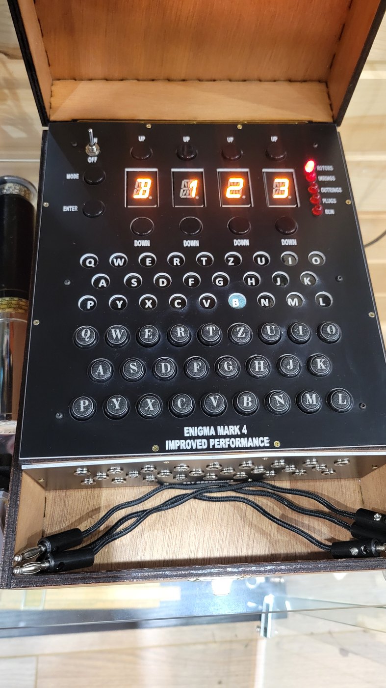
There are 26 banana jacks in a black perforated plate, in the wartime QWERTZ arrangement — Q W E R T Z U I O on the top row, A S D F G H J K in the middle, P Y X C V B N M L at the bottom — with each letter printed above its jack and “S&T GEOTRONICS” engraved along the bottom edge. The kit’s 20 banana plugs and cloth-covered wire make ten cords, each a single conductor with a plug at each end. On my machine the panel stands vertically below the keyboard’s front edge, and the cords lie in the compartment in front of it, as the photographs show. This is the arrangement the “Improved Performance” model was designed for: its box is longer than the original kit’s, so that the lid closes with the cords in place.
The simplification is the cord. A wartime cord had two wires and crossed them; a banana cord has one wire and crosses nothing. It only joins two jacks electrically. Nothing about a single wire says “swap”. The replica gets reciprocity in software: the firmware detects that two jacks are joined and records each letter as the other’s partner, and the cipher routine applies that table on the way in and on the way out, exactly as the double pass through the wartime board did.
17.4 How It Is Wired
The panel’s 26 jacks are soldered to the plugboard PCB, a narrow board that sits directly behind the plate. S&T’s assembly sheet covers it in three steps: solder a block of thirteen double-row header pins to the board; fit the 26 jacks “making sure rounded side of nuts are on PCB side”; then run a ribbon cable from the daughter card (black wire, pin 1, to the left) to the plugboard (cable at the bottom right, black wire “under the ‘L’”). Thirteen double-row pins make 26 contacts: one per jack.
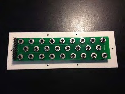
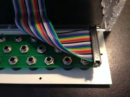
There is no matrix and no multiplexing here. Each jack goes to its own pin on the Arduino Mega. The firmware’s pin table — line 39 of S&T’s Open Enigma M4 Plugboard.ino — gives the mapping for jacks A to Z in order:
//Define Plug Board Pins
int plug[26] = {A14, 49, A12, A15, 7, 53, 50, 52, 3, A6, A4, A11, A9, A10,
                8, A7, 6, 4, 51, 10, 9, A5, 5, A8, A13, 2} ;
So jack A is analogue pin A14 (used here as a plain digital pin), jack B is digital pin 49, jack C is A12, and so on to jack Z on digital pin 2. The scatter of pin numbers is what a board designer gets when routing 26 traces across a crowded two-layer board, not a code.
Twenty-six spare pins are a lot to find, even on a Mega. Comparing S&T’s two published sketches shows where some of them came from. In the sketch for the machine without a plugboard, the lampfield’s nine column lines run to digital pins 2 to 10. In the plugboard sketch those same pins — 2, 3, 4, 5, 6, 7, 8, 9 and 10 — are all plug jacks, and the lampfield’s column lines have moved onto pins that the display segments already use. The lamps and the display segments now share their cathode lines, taking turns in the multiplex. (The old pin list is still in the plugboard sketch, commented out: //int lamppin[12] = {2,3,4,5,6,7,8,9,10,11,12,13}; //2 to 10 cathode, 11 to 13 common annode.) This comes from reading the code rather than from any S&T statement, but it implies that the plugboard machine is not simply the original circuit with jacks added: the daughter card’s routing differs, which fits S&T selling the plugboard version’s boards as a separate “PCB Trio”.
The plugboard version of the daughter card also gains the row of 1 kΩ resistors r31 to r57 (Volume 16). S&T does not say what they are for. The firmware sets the jack pins as plain INPUT, without the microcontroller’s internal pull-up resistors, so something external must hold an unconnected jack at a definite logic level; pull-ups on the plug lines are the obvious candidate. That is an inference.
17.5 How the Firmware Reads the Cords
Here is the routine that turns cords into pairs, from lines 624–642 of the plugboard sketch, lightly reformatted:
void readplugs() {
  for (int index = 0; index <= 24; index++) {
    pinMode(plug[index], OUTPUT);
    digitalWrite(plug[index], LOW);           // pull this jack low...
    for (int indexb = index + 1; indexb <= 25; indexb++) {
      int plugvar = digitalRead(plug[indexb]);
      if (plugvar == 0) {                     // ...any later jack that follows it low
        pluguse++;                            //    is cabled to it
        plugval[0][index] = 1;  plugval[0][indexb] = 1;
        plugval[1][index] = indexb;  plugval[1][indexb] = index;
      }
    }
    pinMode(plug[index], INPUT);              // release it, try the next jack
  }
  plugred = 1;                                // remember that the board has been read
}
It is a continuity tester. Every jack normally reads high (held there, presumably, by the pull-up resistors described above). The routine takes jack A, drives it low, and reads every later jack, B to Z. Any jack that reads low must be joined to A by a cord. Then it releases A, drives B low, and checks C to Z; and so on to Y, which only needs checking against Z. When it finds a joined pair it does two things: it marks both letters as “in use” (plugval[0]), and it writes each letter’s partner into the substitution table (plugval[1]). That table starts as the identity — A goes to A, B to B — so letters with no cord pass straight through, exactly like an empty wartime socket. pluguse counts the pairs.
In the cipher routine, mode5(), the table is applied at the start, procesval = plugval[1][procesval];, and the same line appears again at the end, after the signal has come back from the reflector. That is the wartime double pass, in software.
The crucial line is not in readplugs() but in the routine that runs PLUGS mode:
void mode4() {
  if (plugred == 0) { readplugs(); }
  ...
The board is read only if it has not already been read. The first time the machine enters PLUGS mode after power-on, plugred is still 0, so the scan runs and sets plugred to 1. Every later visit to PLUGS skips it. Nothing else in the sketch resets plugred, so the jacks are not read again until the power is switched off and on.
17.6 Hardware Pairs Plus Software Pairs
After the scan, PLUGS mode carries on as it does on a machine without a panel. The four displays offer a pair as “x TO y” — A TO B at the start — with the left UP/DOWN keys choosing the first letter and the right UP/DOWN keys choosing the second. ENTER commits the pair. Letters that are already in use, whether from a cord or from an earlier ENTER, are skipped, so the display only ever offers free letters. After cords have joined A–Z, B–E and C–D, for example, the first pair offered is F TO G: the first two letters with no cord. (Gleason’s guide shows exactly this, telling the operator to press MODE “when FTOG appears”.)
So the physical panel does not replace the software plugboard; it adds to it. Pairs from the cords and pairs entered by hand go into the same table and the same count. When pluguse reaches ten, PLUGS mode stops offering pairs and shows DONE:
if (pluguse <= 9) { ...offer a pair... } else { done(); }Three details of this design matter in use.
- The ten-pair ceiling applies to hand entry, not to the scan.
readplugs()itself counts every joined pair it finds, with no limit. The kit’s ten cords make the question academic, but eleven or thirteen cords (made up separately) would all be read and used. They would simply leave no room for hand-entered pairs. - Hand-entered pairs cannot be removed. There is no “unplug” key. A mistaken pair stays until the power is cycled.
- A visit to PLUGS cannot be skipped. MODE steps strictly through ROTORS, INRINGS, OUTRINGS, PLUGS and RUN in order, so the first trip to RUN always passes through PLUGS, and the cords are always read before the first letter is enciphered. Gleason’s guide says, for machines with the panel: “Skip if using hardware plugs! Press
.” In other words, the operator passes straight through PLUGS without entering anything, and the scan happens anyway.
17.7 The Practical Rules
Everything above reduces to a few rules for operating a panel-equipped Open Enigma. The first comes straight from Gleason’s guide; the rest follow from the code.
- Cable the board before switching on — or at least before the first visit to PLUGS. Gleason: “If you want to use the hardware plugs, insert them BEFORE you turn on the machine.”
- A cord moved after the first visit to PLUGS does nothing. The table was built during the scan, and the machine goes on enciphering with it. To change the plugging, change the cords, then switch off and on and set the rotors, rings and positions again. (The settings are lost at power-off anyway; see Volume 16.)
- Check the plugging on the display. On entering PLUGS, the first pair offered is made of the two lowest uncabled letters. With all ten cords in, the display should go straight to DONE. If it offers a pair instead, a cord has not been detected — a plug not fully home, or a broken conductor — and the display shows which letters are still free.
- Do not mix accidentally. A pair entered by hand on top of a full set of cords is impossible (the board will already show DONE), but with fewer cords any ENTER adds a pair that the key sheet may not contain.
Rule 2 is a reading of the published code, and it can be tested in a minute without a simulator. With the machine at its defaults (ROTORS B 1 2 3, reflector B, rings and positions all A), in RUN mode:
Table 1 — Rule 2 is a reading of the published code, and it can be tested in a minute without a simulator. With the machine at its defaults (ROTORS B 1 2 3, reflector B, rings and positions all A), in RUN mode
| Setup | Type | Expected lamps |
|---|---|---|
| No cords | AAAAA | BDZGO |
| One cord, A to B, fitted before switching on | AAAAA | BJLCS |
| One cord, A to B, fitted before switching on | BBBBB | ADZGO |
All three were computed with the reference simulator used throughout these volumes (Volume 19). To test rule 2, switch on with no cords, step through PLUGS to RUN, then plug in the A–B cord, switch back round to OUTRINGS, reset the positions to AAAA, return to RUN and type AAAAA. If the code is read correctly, the lamps will still spell BDZGO, not BJLCS: the cord was fitted after the scan and is ignored.
17.8 What the Panel Teaches
On a wartime Enigma, the plugboard was the part the operator touched most often, cord by cord, every day; it was also the part the Bombe was designed to see through, by making deductions that hold whatever the steckering (Volume 10). On the Open Enigma it is the one part of the cipher that is physical rather than computed, even if the computing starts as soon as the cords are read. Pulling ten cords out of their compartment and pushing them into the jacks, one pair at a time from a key sheet, is the closest the replica comes to the hands-on drill of a German signals room. Volume 19 uses all ten to reproduce a real U-boat signal of 1942.
Next — Volume 18: Rewriting the Firmware — My Name in Lights. The scrolling banner at power-on is not a string but a table of numbers, read four at a time onto four sixteen-segment displays. The next volume opens the sketch in the Arduino IDE, decodes S&T’s font and marquee, and shows what it takes to make the displays say something else.
Comments (0)