Enigma · Volume 16
Enigma — Volume 16 — My Open Enigma: The Build
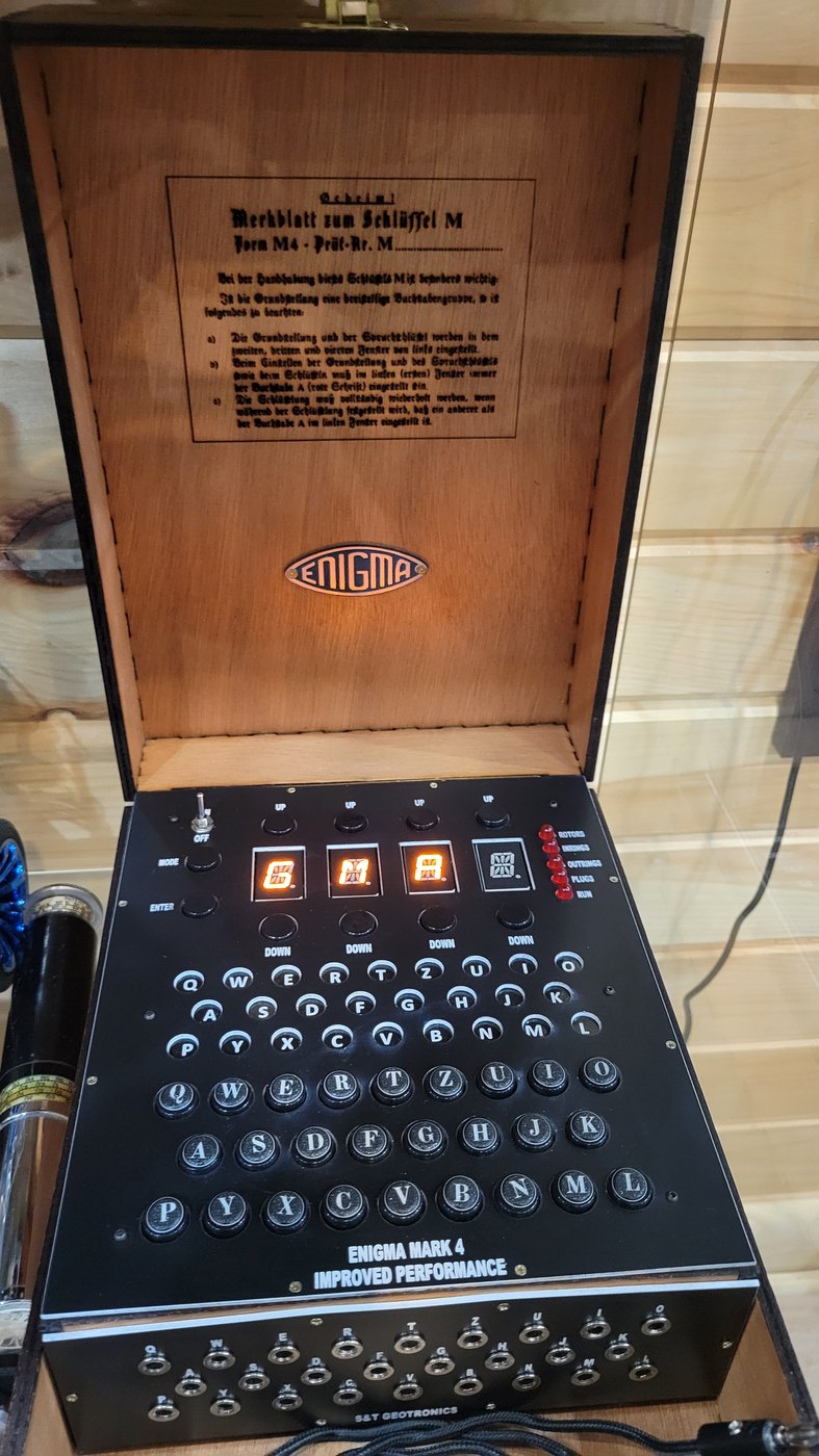
Three circuit boards, an Arduino, a wooden box, and an instruction card from 1940s naval signals printed inside the lid
16.1 About This Volume
Volume 15 described the Open Enigma as a project and a product. This volume is about one machine: mine. I built it from S&T GeoTronics’ kit, and it is an Enigma Mark 4 “Improved Performance”, the name printed in white across the foot of its black top plate. It now lives in a glass display cabinet, on the shelf above some of my slide rules.
The volume covers what comes in the kit and what each part is for; the three circuit boards and how the keyboard, lamps and displays are wired to the Arduino; the assembly sequence as S&T documents it; the wooden case and the instruction card printed inside its lid; and what happens at first power-on, including the five operating modes. The next three volumes take up the three things that make this machine particularly mine: the plugboard front panel I added (Volume 17), the firmware change that puts my name in lights (Volume 18), and the messages it has sent (Volume 19).
Where a passage describes what the kit is and how S&T says to build it, it is written as reference. Where it describes what I did, it says so.
16.2 What Came in the Kit
S&T’s assembly instructions for the plugboard version — Open Enigma Mark 4 with Plugboard: Assembly Instructions — open with a parts list and the advice to check it before starting. It is worth reading in full, because almost every line of it maps onto something visible on the finished machine.
Table 1 — What Came in the Kit
| Qty | Part | What it becomes |
|---|---|---|
| 1 | Motherboard PCB | The user-interface board under the top plate |
| 1 | Daughter Card PCB | The board that carries the Arduino Mega |
| 1 | Plugboard PCB | The board behind the front jack panel |
| 1 | Arduino Mega2560 clone | The brain |
| 4 | LTP587 sixteen-segment displays | The four “rotor windows” |
| 26 | White LEDs | The lampfield |
| 5 | Red 5 mm LEDs | ROTORS, INRINGS, OUTRINGS, PLUGS, RUN |
| 36 | 12 mm push-buttons with caps | 26 letter keys and 10 function keys |
| 29 / 63 / 5 | 470 Ω / 1 kΩ / 10 kΩ resistors | Current limiting, the keyboard ladders, pull-ups |
| 7 | IRF9Z24N P-channel MOSFETs | Anode switches for the displays and lamp rows |
| 1 | On/off/on switch | Power, and a CHARGE position |
| 2 + 1 | 3.7 V 18650 Li-Po cells, dual holder | Internal battery |
| 1 | 8.4 V charger | Charging through the switch’s CHARGE position |
| 1 + 1 | Perforated top plate, perforated plugboard plate | The two black panels |
| 2 | Enigma logos | The badges |
| 26 / 20 | Banana jacks / banana plugs | The plugboard: 26 sockets, 10 cords |
| 1 | Cloth-covered wire | The cords themselves |
| — | Header pins (male, female, double-row) | Board-to-board connections |
At the bottom of the list, under “Optional & Not Included”, come a wood box, two hinges and a half-mortise lock. The software line names a sketch to be downloaded from www.openenigma.com. That site is now dead; the code survives on GitHub, as Volume 18 describes.
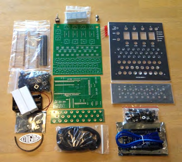
Two numbers on that list say a lot about the machine’s design. The first is the ten cords (twenty plugs). Ten pairs was the standard Army and Air Force practice from 1939, and it is also the limit of the Open Enigma’s software plugboard; Volume 17 explains both. The second is the 36 buttons. A wartime Enigma had 26 keys, and its settings were made by hand: rotors lifted out and swapped, rings turned with a thumbnail, wheels clicked round in their windows. On the Open Enigma, all of that is done with ten extra buttons — MODE, ENTER, and four UP and four DOWN keys, one pair for each display.
16.3 The Three Boards
16.3.1 The motherboard: everything the operator touches
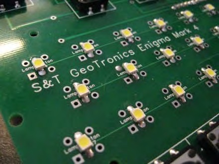
The motherboard sits directly under the black top plate and carries everything the operator sees and touches: the four displays, the five red mode LEDs, the 36 push-buttons and the 26 lampfield LEDs. The lampfield LEDs are small surface-mount packages. S&T’s instruction is to solder them “using center holes, making sure the corner notch is at top right corner”, and to pre-tin both pads first. IEEE Spectrum’s Stephen Cass, building the kit in 2014, found that these parts “can easily slip out of place” while being soldered.
16.3.2 The daughter card: where the Arduino lives
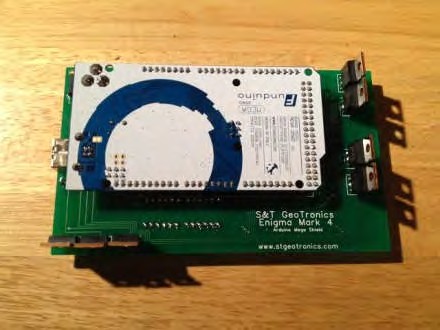
The daughter card plugs in behind the motherboard, and the Arduino Mega snaps onto its back. It carries the 470 Ω current-limiting resistors and the seven MOSFETs, and its header pins carry the Mega’s signals up to the motherboard. On the plugboard version it also carries a row of 1 kΩ resistors “at bottom of board” (positions r31 to r57) — 27 positions, one more than the 26 jacks. S&T’s sheet does not say what they are for. Because the firmware reads the jack pins as plain inputs, without the microcontroller’s internal pull-ups, the likeliest explanation is that they are external pull-up resistors for the plug lines; that is an inference, not something S&T states.
16.3.3 The plugboard PCB
The third board carries the 26 banana jacks and sits behind the front panel, connected to the daughter card by a ribbon cable. It is the subject of Volume 17.
16.3.4 How the lamps, keys and displays are wired
S&T’s two schematic sheets, drawn by Sanderson and Tessier and dated 12 October 2013, show how so much is driven from one microcontroller.
The displays are four Lite-On LTP587 sixteen-segment units, each with 17 segments (16 plus a decimal point) and a common anode. All four share the same 17 cathode lines, each through its own 470 Ω resistor; four of the MOSFETs switch the anodes. The firmware lights one display at a time, sets its 17 segments, waits three milliseconds, blanks it and moves to the next. Done fast enough, the eye sees all four lit at once.
The lampfield is the same idea on a smaller scale: three rows of LEDs (nine, eight and nine, following the QWERTZ rows), with the remaining three MOSFETs switching the row anodes and one cathode line per column.
The keyboard uses no matrix at all. The schematic shows the 36 switches strung along four chains of resistors, each chain feeding one of the Mega’s analogue inputs, A0 to A3. Pressing a key taps the chain at a particular point, so each key produces its own voltage. The firmware’s readkbde() routine reads all four inputs and looks the voltages up in a table of 36 bands. That is how 36 keys cost only four pins.
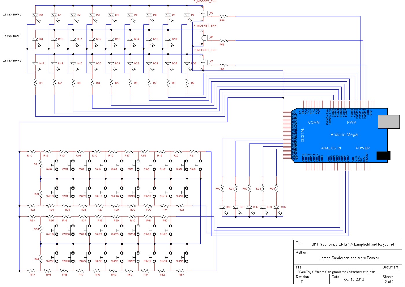
The sketch’s own header sums this up: “The 115 light emitting diodes are multi-plexed to minimize the amount of pins needed down to 38 and all 36 pushbuttons keys are sharing a total of 4 pins.”
16.4 The Assembly Sequence, as S&T Documents It
S&T’s sheet runs to 24 numbered steps and begins: “Read through the following instructions once completely before starting the assembly.” Condensed, the sequence is this.
Motherboard (steps 1–7).
- Three 10 kΩ resistors (r59–r61).
- Thirty-seven 1 kΩ resistors (r1–r11, r50–r58, r62–r78). Many of these form the keyboard ladders.
- The four sixteen-segment displays, decimal point at the bottom.
- The five red mode LEDs, with the anode (the longer leg) on the side marked A.
- All 36 push-buttons.
- The 26 lampfield LEDs, surface-mounted on the centre pads, corner notch to the top right, pads pre-tinned.
- The two 30-pin male header rows, long ends on the resistor side.
Daughter card (steps 8–15).
- The 29 resistors of 470 Ω.
- One 10 kΩ resistor (r40), and the 1 kΩ resistors r31–r57 “at bottom of board”. The sheet marks this step “UPDATED”. 10–14. The header pins: two groups of eight male pins, two 30-pin female rows, a group of six and two of eight, then a block of eighteen double-row pins (Mega pins 20 to 55) and another block of thirteen. The sheet repeats one warning at every step: long ends toward the Arduino side, not the resistor side.
- The seven MOSFETs, following the silkscreen outline.
Bring-up and power (steps 16–19).
- Test first from the computer’s USB power. Only then wire the battery holder, the power connector and the on/off/on switch to the daughter card’s power input.
- Snap the Arduino Mega onto the back of the daughter card.
- Snap the daughter card behind the motherboard.
- “The assembly is complete & ready to test. Power your Open Source Enigma Replica & test all functionality.”
Plugboard (steps 20–22).
- Solder a block of thirteen double-row pins to the plugboard PCB, then fit the 26 banana jacks, “rounded side of nuts” toward the board.
- Connect the ribbon cable to the daughter card, black wire (pin 1) to the left.
- Connect the other end to the plugboard, cable at the bottom right, black wire “under the ‘L’”.
Mechanical (steps 23–24).
- Once everything tests good, screw the stack together with #2-56 screws: two through the Arduino into the daughter card, three from the motherboard through the daughter card, and six through the top plate, with nuts as spacers. Lock each screw with a drop of paint or nail polish. “Tighten firmly but do not over tighten, to avoid cracking top plate.”
- “CONGRATULATIONS! Assembly is complete. Enjoy Encrypting & Decrypting.”
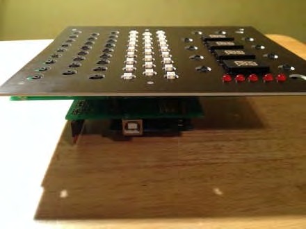
The order has a logic worth noticing. The low, flat parts go on first and the tall ones last, so the board can lie flat on the bench while each row is soldered. All the delicate lampfield work is finished before the headers make the board awkward to handle. And everything is tested on USB power before the battery is connected or the stack is screwed together, so that a fault is found while every joint can still be reached.
16.5 Power
The Open Enigma runs from two internal 3.7 V 18650 lithium cells in series, so it needs no mains lead in use. The three-position switch on the top plate is labelled ON / OFF / CHARGE on S&T’s plate. BJ Gleason’s user guide, Open Enigma for Dummies, gives the routine: turn the switch to CHARGE and plug in the 8.4 V charger. Its light shows blue while charging and red when charging is complete, and the machine cannot be used while it charges.
Because the cells are inside, the machine can sit in a display cabinet or be carried to a table without any cable trailing from it — much as a wartime Enigma ran from its own battery, which is part of why soldiers could carry it into the field.
16.6 The Case and the Merkblatt
The kit itself is a stack of boards under a top plate. The box is what makes it look like an Enigma. Mine is a finger-jointed wooden case with a dark top edge, a brass latch at the front, and a hinged lid. Inside the lid are an oval Enigma badge and, printed onto the wood, a reproduction of a wartime instruction card.
The card is headed Geheim! (“Secret!”) and titled “Merkblatt zum Schlüssel M — Form M4 — Prüf-Nr. M ……”: the instruction sheet for Key M, M4 form, with a blank for a check number. Its text, as printed in my lid, reads:
Bei der Handhabung dieses Schlüssels M ist besonders wichtig: Ist die Grundstellung eine dreistellige Buchstabengruppe, so ist folgendes zu beachten: a) Die Grundstellung und der Spruchschlüssel werden in dem zweiten, dritten und vierten Fenster von links eingestellt. b) Beim Einstellen der Grundstellung und des Spruchschlüssels sowie beim Schlüsseln muß im linken (ersten) Fenster immer der Buchstabe A (rote Schrift) eingestellt sein. c) Die Schlüsselung muß vollständig wiederholt werden, wenn während der Schlüsselung festgestellt wird, daß ein anderer als der Buchstabe A im linken Fenster eingestellt ist.
In English:
When handling this Key M, it is especially important: If the basic setting (Grundstellung) is a three-letter group, observe the following: a) The basic setting and the message key are set in the second, third and fourth windows from the left. b) When setting the basic setting and the message key, and while enciphering, the letter A (red lettering) must always be set in the left (first) window. c) The encipherment must be repeated in full if it is found during encipherment that a letter other than A was set in the left window.
This is not decoration. It records the most important compatibility trick of the four-rotor machine. As Volume 6 explains, the M4 squeezed a fourth, non-stepping Greek wheel in beside a new thin reflector. With the Greek wheel at A (and its ring at A), the thin reflector and the Greek wheel together behave exactly like the old wide reflector B of the three-rotor machines. An M4 set that way can talk to M3 machines ashore, and that is what the card tells the operator to do whenever the key in force is a three-letter one. Rule (c) is the drill for the obvious mistake: if the left window has been knocked off A partway through, start again from the beginning.
The Open Enigma obeys the same arithmetic. Its power-on default is the Greek wheel Beta at ring A and position A, with thin reflector B — which is why, as Volume 19 shows, the default machine and a three-rotor Enigma I give identical output for identical settings.
16.7 First Power-On
S&T’s step 19 is simply “Power your Open Source Enigma Replica & test all functionality.” What the firmware does at that moment is set out in the sketch, and confirmed in Gleason’s guide.
When the switch goes to ON, the machine starts in a mode the sketch calls mode 0, with none of the five red LEDs lit. The four displays become a scrolling banner, moving one character every 400 milliseconds. In S&T’s published firmware it reads “S&T GEOTRONICS ENIGMA MARK 4 DT” — the last two letters showing which model is selected. On my machine the banner is different, and Volume 18 explains why. In mode 0 the keyboard is a “typewriter”: pressing a key lights the lamp of the same letter. That makes mode 0 the natural place to test every key and every lamp. Twenty-six presses should light 26 lamps, each under its own letter, and a key that lights the wrong lamp — or none — points to a solder joint or a resistor-ladder fault before any ciphering is attempted.
Also in mode 0, the leftmost UP key changes the model. Each press moves to the next in the cycle: M4 with double-stepping (the default), then M3, then M4 without double-stepping (a deliberately unhistorical option for experiments), then back to the default. The banner’s ending changes to show which is selected.
16.8 The Five Modes
Pressing MODE steps through five operating modes, each marked by its own red LED, and then back to mode 0. The order matters, because it is also the order in which the wartime operator set up a machine from the key sheet.
Table 2 — The Five Modes
| LED | Mode | What the displays show | What the keys do |
|---|---|---|---|
| ROTORS | 1 | Greek wheel and the three rotors, e.g. B 1 2 3 | UP/DOWN under the right three displays choose rotors I–VIII (no repeats). The leftmost pair toggles Beta/Gamma (“B”/“G”); cycling past Gamma changes the reflector, shown by lamp B or C lighting. |
| INRINGS | 2 | The four ring settings (Ringstellung), A–Z | UP/DOWN move each ring. |
| OUTRINGS | 3 | The four start positions (Grundstellung or message key), A–Z | UP/DOWN move each wheel, like turning it in its window. |
| PLUGS | 4 | A proposed pair, e.g. A TO B | Reads the physical plugboard on first entry; then UP/DOWN choose two letters and ENTER adds them as a pair. Shows DONE after ten pairs. |
| RUN | 5 | The four rotor positions, stepping as keys are pressed | Each keypress steps the rotors and lights the cipher letter. |
The defaults at power-on are rotors B 1 2 3 (Beta, I, II, III) with reflector B, rings AAAA, positions AAAA, and no plug pairs. The sketch keeps these settings only in working memory, so turning the machine off returns everything to the defaults. Gleason’s quick-start guide uses this deliberately: to decrypt a message just typed at the defaults, switch off, switch on, go to RUN and type the ciphertext. It also means a key has to be set up again every time the machine is switched on, exactly as a wartime operator set his up at every change of key.
In the three-rotor M3 model, the leftmost display goes blank in every mode and the leftmost keys stop changing the Greek wheel. The machine then looks, and behaves, like an Army Enigma I. One quirk of that mode, which matters if reflector C is used, is set out in Volume 19.
16.9 The Machine on the Shelf
A wartime Enigma was a working tool in a wooden box, carried in a vehicle or bolted down in a U-boat’s radio room. Mine has a gentler life. It sits with its lid open in a glass display cabinet, with slide rules on the shelf below.
What this build teaches is the subject of the series in small. A kit of boards and resistors is not an Enigma. It becomes one in two steps: first the hardware is assembled so that it can light any lamp for any key; then a few hundred lines of code decide which lamp lights. The wartime machine fused those two steps into brass and Bakelite. The Open Enigma pulls them apart, so that each can be seen — and, in the case of the plugboard and the code, changed.
Next — Volume 17: The Plugboard Front Panel. The Steckerbrett was the German Army’s own addition to the commercial Enigma, and the biggest single contributor to its key space. The next volume compares the wartime plugboard with the Open Enigma’s panel of 26 banana jacks, follows the ribbon cable to the Arduino, and shows exactly when — and only when — the firmware looks at the cords.
Comments (0)