KIM-1 · Volume 6
KIM-1 — Volume 6 — The KIM as a Brain — Robots, Controllers and Mike/Microtron
Fifteen spare input/output lines and a hardware timer: why a demonstration board for a $25 chip ended up inside aircraft navigation experiments, radio stations, organs, typewriters and model railways, and how a teenager in New Jersey made one the brain of a robot
6.1 About This Volume
MOS Technology built the KIM-1 to sell a microprocessor, and the way to sell a microprocessor in 1976 was to show that it could control things. The board’s manual says so on its first pages: the KIM-1 “is intended to provide you with a capable microcomputer for use in your ‘real-world’ application”. This volume follows that intention. It explains what made the KIM-1 a practical controller — the spare 6530 chip with its fifteen input/output lines and its interval timer — and then looks at what people actually connected it to: aircraft navigation receivers, amateur radio stations, typewriters, music synthesizers, model railways, clocks and, most famously, robots.
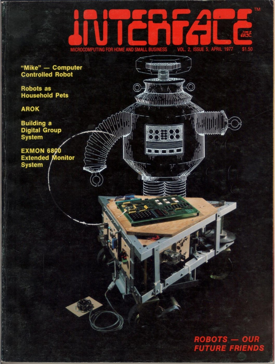
The best-documented KIM robot is “Mike”, also called “Microtron”, built in 1975–76 by the teenage Tod Loofbourrow of New Jersey and described by him in Interface Age in April 1977 and in a book in 1978. That robot already has its own nine-volume deep dive on this site, Loofbourrow’s Mike/Microtron, which covers its frame, drive train, steering, sensors and 6502 software in detail. This volume does not retell it. It places Mike in the wider story of the KIM as a brain, and points to the relevant volumes of that dive.
6.2 What a Controller Needs
6.2.1 Lines, time and attention
A computer that controls a machine needs three things that a computer for calculation can do without. It needs lines to the outside world: wires it can switch on and off to drive motors, relays and lamps, and wires it can read to sense switches, sensors and signals. It needs a sense of time: the ability to hold an output for exactly so many milliseconds, or to measure how long an input has been in one state. And it needs a way to pay attention to events as they happen, which on a microprocessor means interrupts, signals that make the processor drop what it is doing and run a routine of the programmer’s choosing.
Chuck Peddle, who led the 6502 project, had argued for exactly these things at Motorola and been overruled. At MOS he got them. The 6530 chip, designed by Bill Mensch to put ROM, RAM, input/output and a timer in one package, was in Peddle’s words the place where MOS did “the last thing, which I wasn’t allowed to do at Motorola, the interval timer”:
“Without an interval timer you can’t do real-time control. If you want to make your arm come out this much, you turn the motor on, you time out how long you’ve applied the power, turn it off. That’s how you make your copier work … you have to have a real time base. And you can’t do it by counting program cycles.” (Peddle, CHM oral history, 2014, p. 27)
6.2.2 The KIM-1’s user side
The KIM-1 has two 6530s. One, the 6530-002, is fully occupied running the board: its lines scan the keypad, light the six digits, and serve the teletype and cassette interfaces (Volume 3). The other, the 6530-003, is left almost entirely to the owner. The KIM-1 User Manual explains the arrangement:
“The I/O pins provided on the 6530-002 are dedicated to interfacing with specific elements of the KIM-1 system including the keyboard, display, TTY interface circuit, and audio tape interface circuit. The 15 I/O pins on the 6530-003 are brought to a connector and are available for the user to control a specific application. … The interval timer on the 6530-003 array is available for a user defined application program and is not required by the operating programs.” (KIM-1 User Manual, 1976, ch. 3; scan at bitsavers)
Those fifteen lines are the eight lines of port A, PA0 to PA7, and seven of the eight lines of port B, PB0 to PB5 and PB7; the manual’s appendix on the 6530 explains that PB6 “was used as a chip select and is not available to the user”. Each line can be made an input or an output, one bit at a time, by writing to a data-direction register; the port data and direction registers sit at addresses 1700 to 1703 hexadecimal, so a program reads a sensor or switches a relay with a single load or store instruction. The lines are TTL-compatible: they can drive a transistor or a logic gate directly, but a motor or relay needs a driver stage.
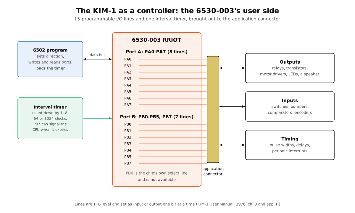
The interval timer counts down from a value the program loads, decrementing once every 1, 8, 64 or 1,024 clock cycles depending on which address the value is written to. At the KIM’s 1 MHz clock that gives intervals from a microsecond up to about a quarter of a second (262,144 clock periods). The program can poll the timer to see whether it has run out, or let it raise an interrupt on the line it shares with PB7. The KIM’s interrupt vectors, the addresses the 6502 jumps to on an interrupt, are kept in RAM at 17FA to 17FF, so that an owner’s program can point them at its own routines. The board’s ST key is wired to the 6502’s non-maskable interrupt, which is how it stops a running program.
The application connector is the lower of the KIM’s two 44-pin gold edge connectors. It also carries the power supply connections and the cassette and teletype lines, so in practice everything except the expansion bus went in and out through one plug. The manual’s one worked application, in chapter 5, is a tone generator: a square wave on PA0, through a simple driver, to a loudspeaker, with its pitch set by seven toggle switches on PA1 to PA7. It is a toy, but it shows every element of control at once — outputs, inputs and timing — on the basic board.
6.3 “Bury Them in Their Products”
6.3.1 A computer cheaper than designing one
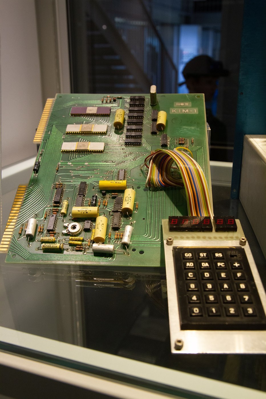
The KIM-1’s price changed what it was used for. MOS meant it as a development system: an engineer would try out the 6502 on it, then design a custom board for the product. Many skipped the second step. Bob Yannes, then at MOS, described the pattern to Brian Bagnall: customers would say, “Why do we want to design our own computer? We have one right here and it’s only [$245], which is cheaper than we can build it for.’ They would just buy KIM-1’s and bury them in their products” (Bagnall, On the Edge, ch. 1.5). Robert M. Tripp, writing in Kilobaud in August 1977, estimated that there were “over seven thousand KIM-1s in the field” and that “these are being used mostly by industry”, with schools and hobbyists making up the rest (Tripp, “Is the KIM-1 for Every-1?”).
The industrial users mostly did not write about it, so the evidence is indirect: the laboratories, instrument makers and universities among the early KIM-1 User Notes subscribers; suppliers such as Hybrid Technologies of Pennsylvania advertising relay boards for the KIM in BYTE; and a letter in User Notes issue 6 (July 1977) from a reader announcing a small 6505-based controller board, who explained why: “I have designed the KIM into a number of projects and then wished that it had a dedicated controller to perform that task so that the KIM would be free for other things.” The answer to that wish, a few years later, was the single-chip microcontroller; but for a while, the KIM-1 itself was the cheapest programmable controller most engineers could buy.
6.3.2 Documented uses
Some uses are documented in detail.
Aircraft navigation. At Ohio University’s avionics engineering centre, J. D. Nickum built a “stand-alone development system using a KIM-1 microcomputer module”, reported to NASA in March 1978 (NASA CR-156067). It was small enough “to be strapped to the seat of a light general aviation aircraft”, ran from its own power, and was used “to develop a low cost Loran C sensor processor”, with plug-in interface boards that could be swapped for other experiments (NASA Technical Reports Server). BYTE in March and April 1977 published a Mini-Omega navigation receiver that used a KIM or the similar JOLT board for its signal processing.
Amateur radio. The very first issue of User Notes after the complimentary one carried a reader’s plan to use the application connector to drive a touch-tone encoder chip, storing telephone numbers and controlling a local 2-metre repeater from his car, and reported that other radio amateurs were “using their systems for contact logging, Morse Code generation and the control of frequency synthesizers and frequency readout units”. 73 Magazine in September 1977 showed how to make the KIM’s LED display read out radioteletype signals fed into its cassette input.
Typewriters, clocks and railways. BYTE in June 1977 ran “Teaching KIM to Type”, on driving an IBM Selectric typewriter as a printer, and “Designing Multichannel Analog Interfaces”, on an eight-channel analogue input system for the KIM. Interface Age in August 1977 published “A KIM-1 Sidereal/Solar Clock” for astronomers. User Notes reported a seminar in Cleveland on a “computer controlled model railroad using the KIM (what else). Very impressive.”
Music. Music was the most striking demonstration of control by timing alone. Butterfield’s music box in The First Book of KIM toggled one output bit to drive a speaker (Volume 5). At the Trenton Computer Festival in April 1977, Hal Chamberlin, “with just a basic Kim and a handful of parts”, made it play the theme from Exodus in four-part harmony, an achievement that User Notes called the most fantastic demonstration of the show. Chamberlin’s article in BYTE in September 1977, “A Sampling of Techniques for Computer Performance of Music”, explained the methods, and his company, Micro Technology Unlimited, sold music boards for the KIM and later the PET.
6.4 Techniques: How a KIM Drives a Machine
The KIM-1 programs of the period used a small set of techniques that are worth naming, because they are still the basis of embedded programming.
Polling. The simplest program loops forever: read the input port, decide, write the output port, repeat. With a 1 MHz 6502 such a loop can run thousands of times a second, which is fast enough to watch a switch or a comparator.
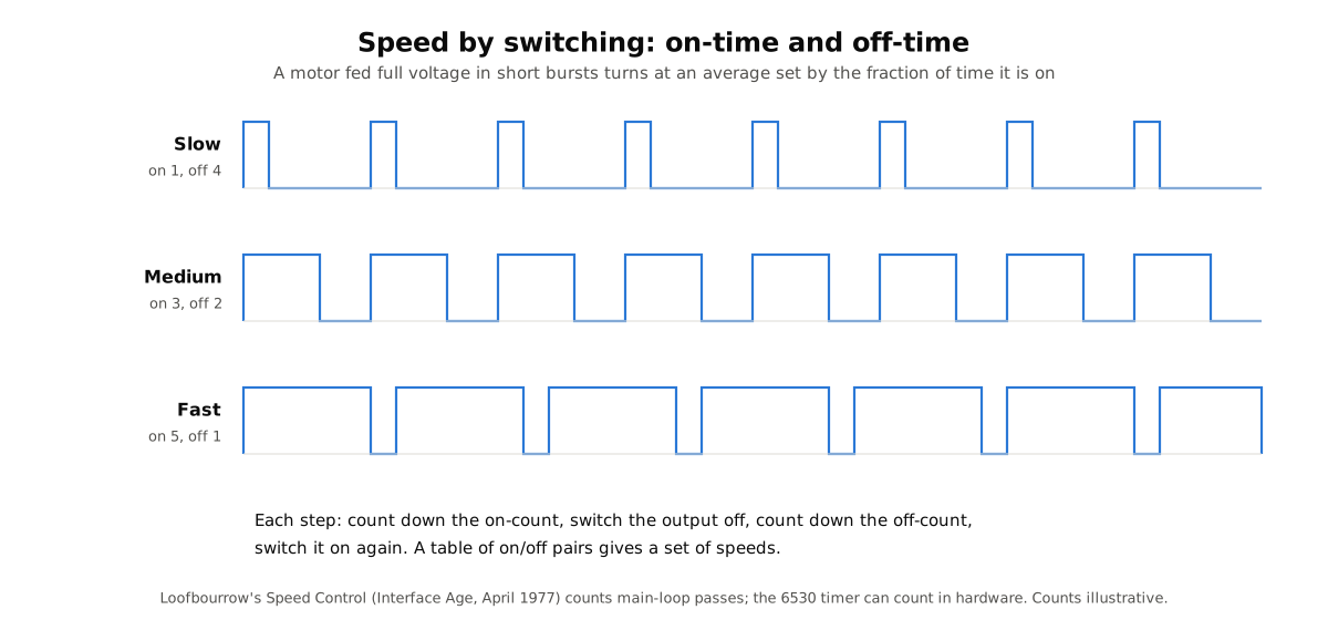
Counting passes. If the loop always takes the same time, the number of passes through it is a clock. A program can turn a motor on for so many passes and off for so many, without touching the hardware timer. The speed of the motor then depends on the ratio of on-passes to off-passes.
The hardware timer. For accurate timing independent of what the loop is doing, the program loads the 6530’s interval timer and either polls it or lets it interrupt. This is the method Peddle had in mind: turn the motor on, start the timer, turn the motor off when the timer runs out.
Switching for speed. A DC motor fed its full voltage in short bursts runs at a speed set by the fraction of time it is on. Varying the on-time and off-time — what is now called pulse-width modulation — gives a range of speeds from one output bit and one transistor or relay.
Thresholds instead of converters. An analogue-to-digital converter chip was expensive in 1976. A comparator was cheap: it compares two voltages and gives a single on/off output. With a comparator on an input line and a capacitor charged through a known resistance, a program can measure a voltage by timing how long the comparator takes to switch. That is how a joystick or a potentiometer was read on a KIM.
6.4.1 Interfacing in practice
Between a 6530 output pin and a motor there was always a chain of parts, and the KIM projects of the period show the same chain again and again. A port line can source or sink only a small current at logic levels, so it first drives a buffer — often an inverter from a 7404 hex inverter package, which also gives a clean logic signal and protects the 6530 from whatever happens downstream. The buffer switches a transistor; the transistor energises a relay coil or, in later designs, drives the motor directly; and the relay’s contacts carry the motor current from a separate battery. Diodes across the coils catch the voltage spike when a coil switches off. Inputs run the other way: a switch pulls a line to ground against a resistor, or a comparator turns a voltage into a clean high or low.
Power was its own problem. A robot or instrument running from a 12 V battery had to make the KIM’s regulated +5 V itself, and motors starting and stopping put noise on every wire. Loofbourrow’s power diagram shows the usual remedy: fuses on every branch, two separate three-terminal 7805 regulators so that the computer’s +5 V supply was kept apart from the +5 V used by the interface logic, and very large filter capacitors on each (Interface Age, April 1977, Diagram B; see Loofbourrow, Volume 5). Three of his KIM’s port A lines, PA1, PA2 and PA3, went through 7404 inverters to become the robot’s Steer Left, Steer Right and Speed Control signals, which in turn drove transistors and Radio Shack relays.
Software and hardware were designed together. Because an inverter sat between the port and the relay, the program wrote a 0 to turn something on; because the port register held the steering bits and the speed bit side by side, the program changed one bit at a time by reading the register, masking the bit, and writing it back, so as not to disturb the others. Those small habits — active-low outputs, read-modify-write on a shared port — are the everyday grammar of controller programming, and the KIM taught them to thousands of people.
6.5 Mike, Also Called Microtron
6.5.1 The robot
Tod Loofbourrow began building a robot in 1975, at fourteen by his own account in Interface Age (Bagnall gives his age as twelve), and gave it a KIM-1 for a brain. He was a member of the Amateur Computer Group of New Jersey. The robot grew in stages. The first was a triangular rolling chassis of angle aluminium with three wheels, one of them steerable, powered by a 12 V car battery, carrying the KIM-1 on a plywood board and driven by a joystick; later stages added ultrasonic ranging, impact switches and feelers to avoid obstacles, and finally a limited ability to recognise spoken commands by matching stored word patterns. Fully built, it stood about six feet tall and weighed about 70 pounds.
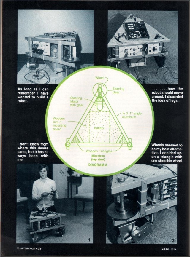
What makes Mike important is that it was documented. The April 1977 Interface Age article — one of the magazine’s robot issue features, headlined “‘Mike’ — A Computer Controlled Robot” — gave the chassis drawings, the power supply, the motor and steering circuits, the comparators that turned the joystick’s potentiometers into signals the KIM could read, the 6502 programs in full, and a flowchart of the control loop. The following year Hayden Book Company published Loofbourrow’s book, How to Build a Computer-Controlled Robot (1978, 132 pages, ISBN 0-8104-5681-8), which Bagnall says he wrote on yellow lined paper. A later account in Inc. magazine put its sales at about 20,000 copies. The robot was also shown at the Trenton Computer Festival in April 1977, the show that User Notes called “Kim’s day all the way” (Volume 5).
6.5.2 How the KIM ran it
Mike shows every technique in the previous section on a real machine, and the robot dive covers each in detail:
- The KIM-1 as brain — what the board provided and how the robot’s circuits connected to it: Loofbourrow, Volume 2.
- Comparators and steering — the RS 339N quad comparator that converted the joystick and steering potentiometers into bits on PA5, PA6 and PA7, and the relay matrix that reversed the steering motor: Loofbourrow, Volume 5.
- Sensing — ultrasonic ranging, impact ribbon switches and feelers, and the voice stage: Loofbourrow, Volume 6.
- Software — the table-driven 6502 programs: a Speed Control routine that switches the drive motor on and off in counted passes to give five forward and five reverse speeds, a Manual Control routine that reads the comparators and looks up speeds in a ten-entry table, and a Steering Table: Loofbourrow, Volume 7.
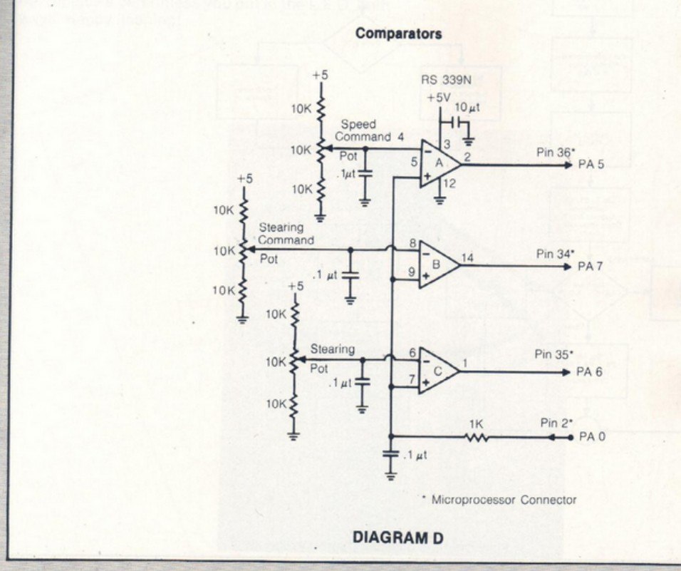
The software is a model of working within a kilobyte. Speeds are stored as on-time and off-time values packed two to a byte; steering is a table lookup rather than arithmetic; the whole control loop, reading three analogue inputs and driving three outputs, fits in a few hundred bytes of the KIM’s RAM.
6.5.3 Other KIM robots
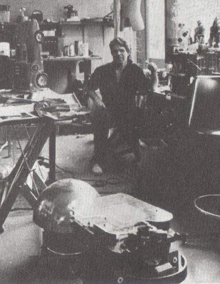
Mike was not alone, though it was by far the best documented. Gene Oldfield’s robot Entropy, begun about 1976, was another three-wheeled machine on a car battery; Oldfield later wrote that “a KIM single-board computer was interfaced to the sensors and relays by only seven microchips”, and that it used sonar to range about fifteen feet and could record and play back sequences of movements from programs held in battery-backed memory (cyberneticzoo.com, citing Oldfield and Bonnet, Everyone Can Build a Robot Book, 1984). Searches of the KIM bibliographies in User Notes and The First Book of KIM turn up no other robot as fully published as these two, though User Notes remarked in May 1977 that “no one has yet found a decent way to package their computer — with the exception perhaps of Tod Loofbourrow, who built a robot around his.”
6.6 After the KIM
The KIM-1’s career as a controller was short for the same reason that it was possible at all: chips kept getting cheaper. MOS and its licensees sold the 28-pin 6504, 6505 and 6507, cut-down 6502s for products that needed less memory; Commodore’s CHESSmate was in effect a KIM-1 rebuilt around a 6504 (Volume 5); Atari’s VCS used a 6507 with a 6532 RIOT, a close relative of the 6530 without the ROM. Rockwell’s AIM-65, with a full keyboard, an alphanumeric display and a built-in printer, became a popular laboratory and industrial controller in its own right (Volume 7). By the early 1980s single-chip microcontrollers combined processor, memory, I/O and timers on one die and made a separate board unnecessary for most control jobs.
What the KIM-1 established was the pattern. A general-purpose computer on a small board, with spare input/output lines and a timer brought out to a connector, sold cheaply enough to put inside a project, programmed by its owner, and supported by a community that shared circuits and code: that is a description of the KIM-1 in 1977, and of the hobbyist controller boards that followed it decades later.
Next — Volume 7: Commodore, the PET and the KIM’s Legacy. Jack Tramiel buys MOS for stock, the KIM-1 gets a Commodore logo, Chuck Peddle turns a single-board computer into the PET 2001, Rockwell and Synertek build their own KIMs, and the original boards become museum pieces.
Comments (0)