Fialka · Volume 9
Fialka — Volume 9 — Building a Fialka — Simulator and Replica Options
The simulators that already exist and who made them, how this series's simulator was checked against them, three ways to build a Fialka, and a full design for an electromechanical replica: ten wheels with removable printed-circuit cores, spring-pin contact plates, blocking pins read by light, a thirty-by-thirty key-card board and a microcontroller doing the work of the motor and cams
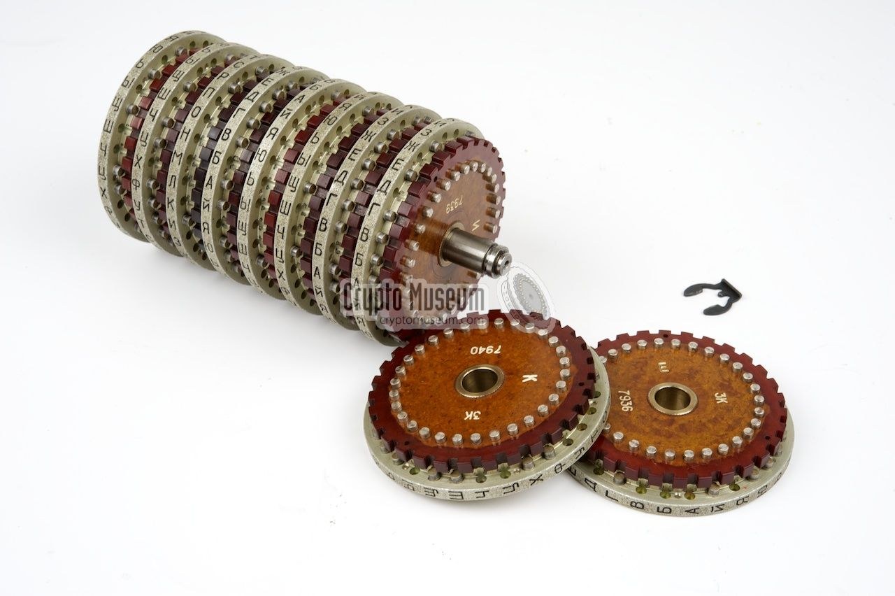
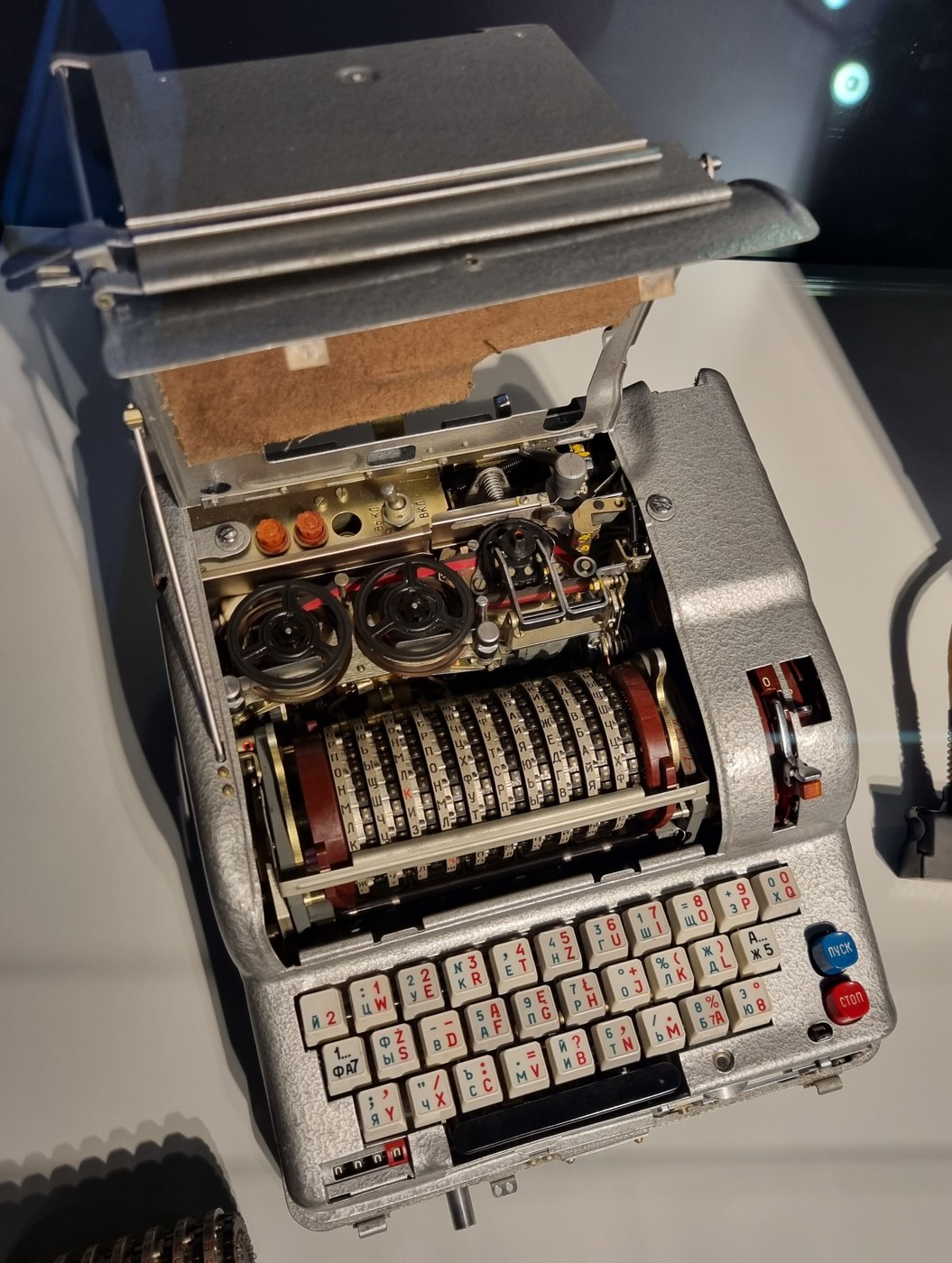
9.1 About This Volume
Surviving Fialkas are rare, heavy and sought after. Most were returned to the Soviet Union and destroyed after 1990, and Volume 8 describes the few that escaped. Anyone who wants to use one has three choices: run a simulation, build a box that behaves like one, or build a machine whose cipher really is done by wired wheels and a punched card. This volume covers all three. It begins with the simulators already published, credits their authors and explains how the simulator used throughout this series was checked against them. It then gives a complete design for the third kind of machine, an electromechanical replica. Its drum, key card and reflector wiring carry the current as the original’s did, but a microcontroller replaces the motor, cams and transport combs. Every part is listed in a printable bill of materials at the end. Volume 10 puts the replica, or the simulator, to work.
The design here is new. No physical Fialka replica has been published that this series could find. The designs it draws on are the SIGABA replica in that unit’s Volumes 10 and 11, which uses the same family of parts, and the reverse-engineering in Reuvers and Simons’s Fialka M-125 Reference Manual.
9.2 What a Replica Has to Do
A machine that deserves the name must reproduce every part of the cipher described in Volumes 3 and 4, and nothing else:
- Ten wheels of thirty contacts, each wired as a published series, that can be put on the spindle in any order and set by hand to any position above a ruler.
- Adjustable wheels: a ring that carries the blocking pins and can be turned against the body, and a wiring core that can be lifted out, put into another body, turned over, and set at any of thirty positions.
- Alternate stepping: two chains, even wheels from wheel 2 and odd wheels from wheel 9, turning in opposite directions and blocked by pins sensed 17 and 20 places on from the ruler.
- A key card that joins thirty inputs to thirty outputs, changeable in seconds.
- The fixed wirings: keyboard to card reader, and card reader to entry disc, with the three-contact offset at each end of the drum.
- The reflector: thirteen pairs, contact 13 printing the plaintext, and the three-point triangle reversed between coding and decoding.
- The operator’s controls: a thirty-key keyboard with space bar, the MODE switch (О, Р, З), and on an M-125-3 the TEXT MODE lever (Б, С, Ц) and the 30 ↔ 10 switch; a letter-group counter; a printed tape in groups of five.
It must also be checkable. A replica that gives a plausible-looking cipher is worth nothing unless it gives the cipher, letter for letter, of the published test strings.
9.3 What Already Exists
Several simulators have been written since Crypto Museum’s work made the machine’s internals public. All of them, including this series’s, depend on Reuvers and Simons’s measurements.
Crypto Museum (Paul Reuvers and Marc Simons, Netherlands). Their Fialka M-125 Reference Manual, first released around 2005–2009 and free since January 2021, is the foundation of all the work that followed. Its section 3.7, “Sequence of Events”, gives the order of every substitution and offset, which the authors checked “against a real Fialka machine” with a simple simulation of their own. Their wiring page publishes the wheel wirings and pin positions of four series, the keyboard, card-reader, entry-disc and reflector tables. A set of XML files “for software Simulator authors” (version 0.10, 25 December 2017) covers the 68, 3K, 5K and 6K wheels (Crypto Museum, “Fialka wiring”).
Vyacheslav Chernov, Fialka Simulator v5.16 (24 October 2014). A windowed Windows program (written in Delphi, according to the Lumenman project below), distributed through Crypto Museum’s Fialka page (Crypto Museum). It has become the reference against which other simulators are tested: both projects below take their test strings from it.
CrypTool 2, Fialka component (Eugen Antal and Tomáš Sovič, Slovak University of Technology in Bratislava, 2016; Apache 2.0 licence). Part of the open-source CrypTool 2 suite. It models the M-125 and M-125-3, fixed (PROTON-I) and adjustable (PROTON-II) wheels, the 3K, 5K and 6K series, the Czechoslovak, Polish and East German layouts, mixed and numbers-only modes. Its unit tests contain 35 encipherments made with Chernov’s simulator, which are the backbone of this series’s checks (source; tests in UnitTests/FialkaTest.cs). Antal is also the author, with Viliam Hromada, of a 2013 paper that turned the Fialka’s design into a modern stream cipher, and, with Pavol Zajac, of the 2015 Cryptologia analysis of its key space and period.
Lumenman, FIALKA (2026, MIT licence). An emulator of the M-125-3 in Free Pascal, with a Python reference model kept in step with it character for character. Its tables were extracted from Chernov’s program and cross-checked against CrypTool 2. It records three further test strings from Chernov’s simulator, covering numbers-only mode and the mixed letter-and-figure mode that the CrypTool tests do not (github.com/Lumenman/FIALKA). Its documentation notes that CrypTool 2’s East German Latin print-head table appears to be corrupted. That table affects only how East German Latin letters are printed, not the cipher.
Hafting, enigma (2016, GPL 2.0). A terminal (ncurses) simulator for Enigma and Fialka machines driven by text files that describe each machine, including a Fialka M-125 file (github.com/Hafting/enigma). This series has not tested it.
Collectors have also made reproduction key cards for original machines; Volume 8 describes them.
9.4 This Series’s Simulator
The simulator used for every example in this series, 03-outputs/tools/fialka_sim.py, is a single file of plain Python with no dependencies. It was written from the primary data rather than translated from any of the programs above:
- Historical: the wirings and pins of the 68, 3K, 5K and 6K series, the keyboard, entry-disc and reflector tables (Crypto Museum XML, 2017); the stepping rules and sensing offsets (Reference Manual 3.3.8); the order of events, the +3 offset and the position, ring and core arithmetic (Reference Manual 3.7).
- Reconstructed: conventions the sources leave implicit, taken from CrypTool 2 and stated as such in the file. These are which way the letters run as a wheel steps, how a flipped core’s wiring is derived (the mirror image, run backwards), the re-routing tables of the 30 ↔ 10 switch, and the special-character rows of the national key tops.
python3 fialka_sim.py --selftest runs 53 checks. Thirty-five are the CrypTool 2 test strings from Chernov’s simulator, from 16 to 690 characters long. They cover both models, both wheel types, all three tested series, three national layouts, wheel order, positions, ring settings, core order, core side, core setting, a punched card, spaces and ten strings in numbers-only mode, with two deciphered as well as enciphered. Three more are Lumenman’s recordings, each run both ways. The rest check structural properties: decoding inverts coding, a letter can encipher to itself, adjustable wheels in the basic setting equal fixed wheels, position and ring setting enter only as their sum, and the reflector has the shape described in Volume 4. All 53 pass.
The tests are sensitive. Changing the even chain’s sensing offset from 17 to 18, the odd chain’s from 20 to 21, or the drum offset from 3 to 0 or 4, makes every one of the 35 published strings fail. Replacing the flipped-core rule with a plausible alternative makes 14 of them fail. The Soviet 68 series is included but untested, because no published string uses it.
The program also prints what this volume’s replica needs for testing:
python3 fialka_sim.py --demo-key                    # the demonstration key (JSON)
python3 fialka_sim.py --key KEY.json --encrypt "…"  # encipher, five-letter groups
python3 fialka_sim.py --key KEY.json --decrypt "…"
python3 fialka_sim.py --key KEY.json --trace F      # one key-press, wire by wire
python3 fialka_sim.py --key KEY.json --steps 40     # positions and stepping, per key
A companion, fialka_attack.py, runs the analysis demonstrations of Volume 10.
9.5 Three Ways to Build One
Table 1 — Three Ways to Build One
| A: software | B: microcontroller box | C: electromechanical replica | |
|---|---|---|---|
| What does the cipher | a PC program | a program in a microcontroller | wired wheel cores, a punched card, a fixed reflector wiring |
| Wheels | on screen | rotary encoders or printed dummy wheels | ten real wheels with removable cores and pin rings |
| Stepping | computed | computed | sensed from real pins, solenoid-driven |
| Key card | typed in | typed in or read from a QR code | punched card over a jumper board |
| Cost (November 2026, rough) | nothing | about $150 | about $800–1,500 |
| Effort | an evening | a few weekends | several months |
| Checkable against vectors | yes | yes | yes, part by part |
Route A is any of the simulators above. Route B puts this series’s simulator, or its tables, into a Raspberry Pi Pico 2 in a grey case with a thirty-key keyboard and a thermal printer. It works exactly, and it is a fine desk object, but its wheels are decoration. Route C is the subject of the rest of this volume. In it the current is real: the controller sends it into the card board and finds it again after it has passed through twenty wheel wirings and the reflector. Every part can be tested, and every part can be wrong in a way that the tests find.
9.6 The Design
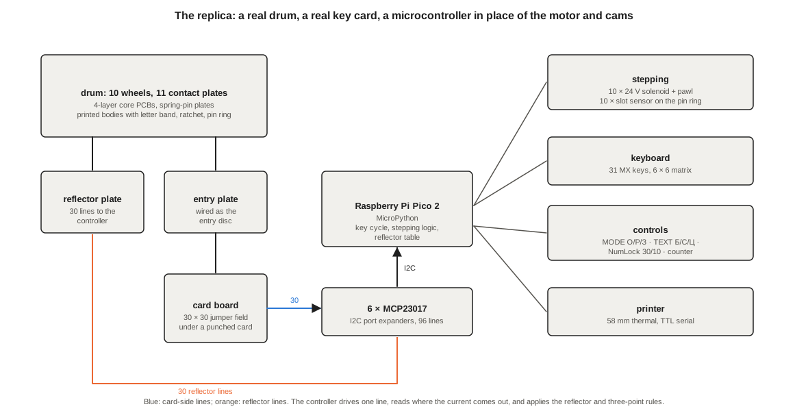
The replica is built around one decision. Everything that the original did with wiring is done with wiring: the wheels, the key card and the entry-disc scramble. Everything that it did with motion and timing is done by the controller: the motor, the cams, the transport combs, the pulse switch and the printer drive. The reflector sits on the boundary. Its pairs and its triangle are a table in the controller rather than a wired disc. That choice makes the three-point circuit and the 30 ↔ 10 loop simple to implement, and it lets the controller detect a broken path at once.
9.6.1 Wheels and Cores
Each wheel has two parts, as the 1978 adjustable wheel does.
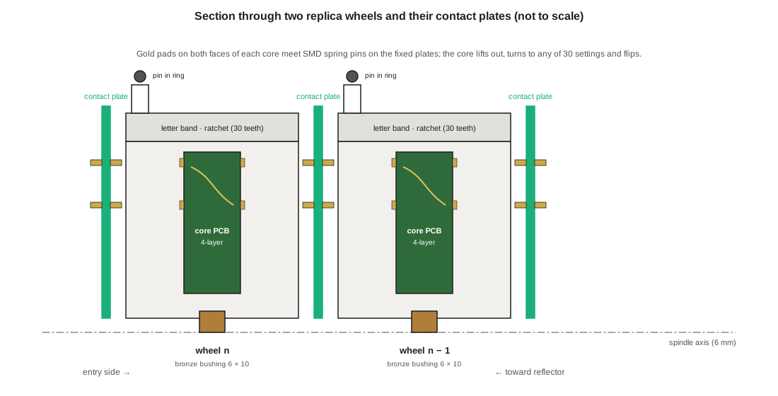
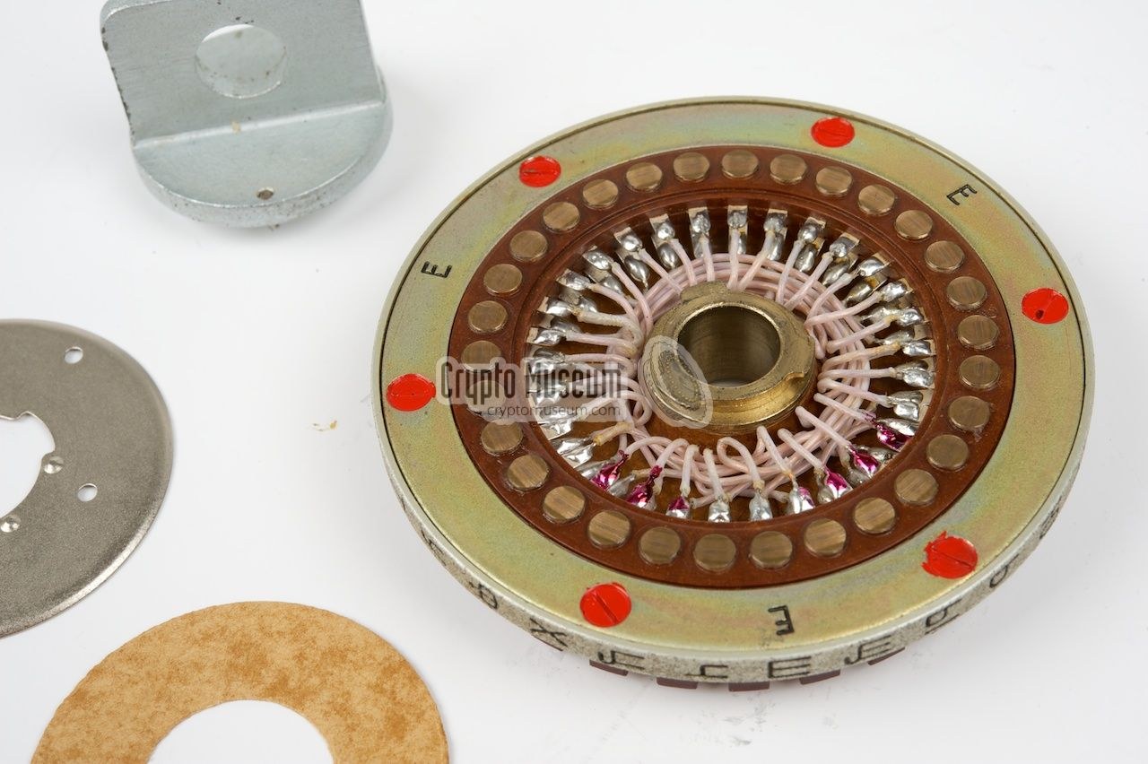
The core is a round printed-circuit board, 56 mm across, four layers, gold-finished (ENIG). Each face carries thirty pads, 2.8 mm across, on a 46 mm circle. The wheel’s wiring, thirty connections from face to face, runs on the two inner layers. There is no hand wiring: a short script reads the wiring table from fialka_sim.py and writes each core’s netlist for the board-layout program, so the ten 6K cores are ten board designs ordered together. The silkscreen carries the core’s letter, “1” on one face and “2” on the other, and a white index mark. Thirty small notches round the edge let the core sit at any of the thirty core settings. Because the pads are the same on both faces, a core turned over simply presents its other face. The mirrored, reversed wiring that Volume 3 describes then follows automatically.
The body is printed in PETG, about 86 mm across and 16 mm wide. Its rim carries a self-adhesive band of thirty Cyrillic letters at 12° spacing, black for an operational set and red for a spare, and a ring of thirty ratchet teeth for the stepping pawl. Inside, a recess holds the core on an index tab, open on both faces so that spring pins can reach the pads. The pin ring is a separate printed ring with thirty 2 mm holes on a 74 mm circle. A sprung latch lets it be turned against the body to any of thirty ring settings. Pressed into its holes are the blocking pins: steel dowel pins 2 × 8 mm, in the positions of the series table. The 6K set needs 138, from seven on wheels В, Д and И to twenty-three on wheel К. The pins stand out from the side of the wheel into the gap beside it, where the stepping mechanism’s sensor reads them.
9.6.2 Contact Plates
The original’s wheels press directly against one another, spring contacts on one wheel against flat contacts on the next. A printed wheel cannot keep thirty springs aligned reliably, so the replica adds a fixed contact plate between each pair of wheels, as the SIGABA replica in that unit’s Volume 10 does. Each inner plate is a 64 mm round board with thirty surface-mount spring pins on each face. Each pin is joined through the board to the pin opposite it, so the plate passes the current straight across from the pads of one core to the pads of the next. The two end plates carry pins on one face only and bring thirty lines out to a 40-way ribbon connector: the entry plate at the right, the reflector plate at the left. The plates are slotted onto a 4 mm tie rod beside the spindle, which keeps them from turning. The wheels turn between them on bronze bushings. The whole drum of ten wheels and eleven plates lifts out as one unit, as the original’s does. The plates use 630 spring pins, including spares; the part chosen, a Mill-Max surface-mount pin with about 5.8 mm working height, is the one used in the SIGABA replica.
The plates make the replica’s drum longer than the original’s, about 22 mm per wheel or roughly 260 mm in all. They cost nothing in fidelity, because a plate passes contact n to contact n.
9.6.3 Stepping
Each wheel has its own stepping unit: a 24 V push solenoid driving a pawl against the wheel’s ratchet. One stroke turns the wheel by one tooth, 12°. The even wheels’ solenoids are mounted in a row behind the drum and push their wheels away from the operator; the odd wheels’ are mounted in front and push them towards the operator. So the two chains turn in opposite directions, as on the original. A spring ball detent on each ratchet centres the wheel on its letter between steps, doing the work of the lock-step arms.
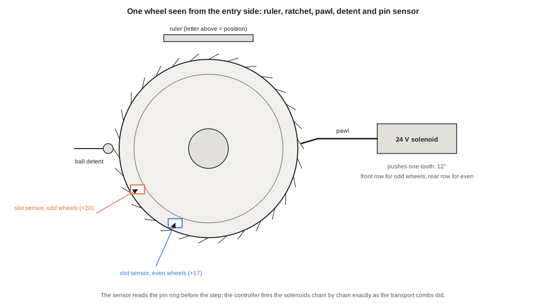
The pin sensor is a slotted optical switch (a Vishay TCST2103, 3.1 mm gap) that straddles the circle of pins at exactly the place where the original’s carry-on finger felt for them. For an even wheel that is 17 positions, 204°, on from the ruler; for an odd wheel 20 positions, 240°. A pin in the slot interrupts the light. Before each step the controller reads all ten sensors and then fires the solenoids chain by chain: wheel 2, then wheel 4 if wheel 2’s sensor is clear, then wheel 6 if wheel 4’s is clear too, and so on; wheel 9, then 7, 5, 3 and 1 in the same way. The controller does not know where any wheel stands. It only knows where the pins are, as the transport combs did, so a wheel set wrongly by hand steps exactly as wrongly as the original’s would.
9.6.4 The Key-Card Board
The card reader is a jumper board: a 170 mm square circuit board with thirty column traces (the inputs, from the controller’s thirty card-side lines) crossing thirty row traces (the outputs, to the entry plate). At each of the 900 crossings stands a pair of 2.54 mm header pins, one joined to the row and one to the column. A key card is printed on stiff paper with the same grid and punched with thirty holes. It drops over the pins, and a jumper pushed through each hole joins one column to one row. This is the original’s arrangement in slower form: one hole in each row and each column, and a short circuit if the card is wrong. The entry-disc scramble is routed on the same board, between the row outputs and the ribbon to the entry plate, so it is fixed in copper as the original’s was. A card punched on the diagonal plays the part of the metal test triangle. The board sits in a drawer at the left of the case.
9.6.5 Reflector and Three-Point Circuit
The reflector plate’s thirty lines go to the controller. To encipher a key, the controller does what the original’s current did, in two phases:
- Out. It holds every line high except the card-side line for the key (after the fixed keyboard scramble, done in firmware) and pulls that one low. The current runs through the card, the entry wiring and all ten wheels to the reflector plate. The controller reads the thirty reflector lines and expects exactly one to be low: the reflector contact r.
- Back. It releases the card-side line and looks up r. If r is 13, it prints the key’s own letter. If r is 16, 18 or 24, it takes the next contact of the triangle in the direction set by the MODE switch. Otherwise it takes r’s partner. It pulls that reflector line low, reads the thirty card-side lines, and expects exactly one low. That line, unscrambled, is the letter to print.
If either phase finds no line low, or more than one, a contact has failed or the card is wrong. The controller then prints an asterisk, as the original’s print head did. In numbers-only mode the controller follows the re-routing tables of the 30 ↔ 10 switch: a current that reaches a dead reflector contact is sent back into the card board on the corresponding input and the phase is repeated until it reaches a live one (Volume 4).
9.6.6 Keyboard, Controls and Printer
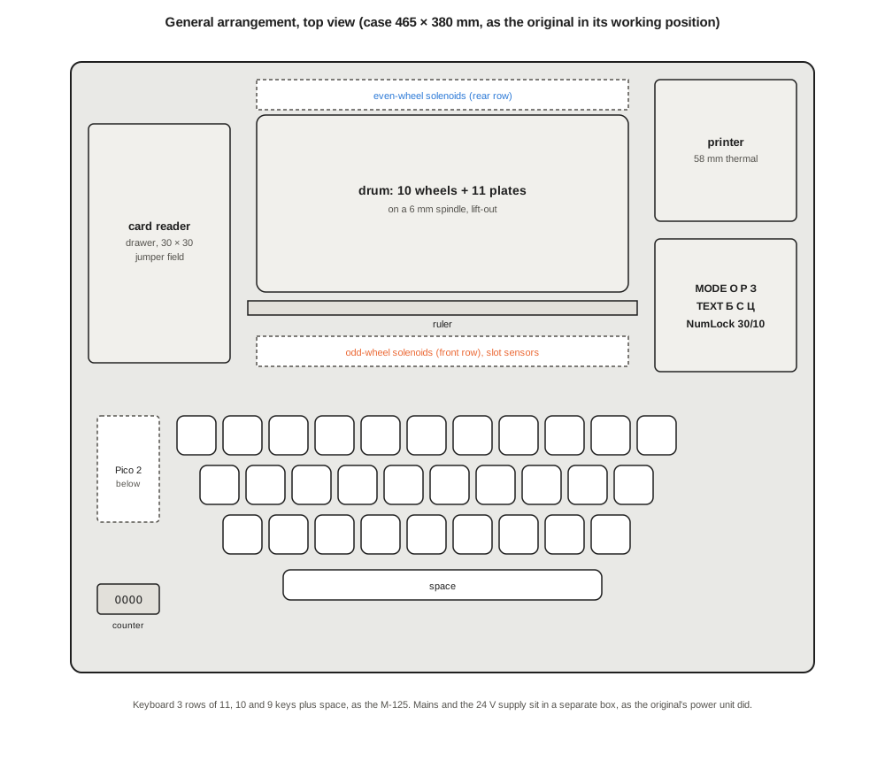
The keyboard has thirty MX-type key switches in three rows of eleven, ten and nine, plus a space bar. They are scanned as a six-by-six matrix with a diode per key. The keycaps are the two-part relegendable kind: a paper insert under a clear cover carries the Cyrillic and Latin legends of whichever national layout is wanted. The MODE switch (О, Р, З) and the TEXT MODE switch (Б, С, Ц) are three-position rotary switches. The 30 ↔ 10 switch is a lever toggle. A four-digit display to the left of the space bar counts letters as the original’s counter did, its last digit to five. Output goes to a 58 mm thermal printer that prints the tape in groups of five. The original’s 17.5 mm punched tape is not reproduced. A builder who wants it can add a five-hole punch or simply write the five-bit code to a file.
9.6.7 Power and Case
The solenoids run from 24 V and the logic from 5 V. The supply lives in its own small aluminium box with a fused, switched mains inlet, as the original’s power unit did, and reaches the machine on a four-pin aviation plug. Inside the box are a 24 V, 4.5 A supply and a 24-to-5 V step-down regulator. The case is folded 1.5 mm aluminium sheet with a hinged lid, painted grey hammer-finish. Its footprint of 465 × 380 mm is that of the original in its working position, as the 1978 manual gives it.
9.7 The Controller’s Cycle
The program, in MicroPython on a Raspberry Pi Pico 2 with six MCP23017 expanders, runs one cycle per key:
- Read the key, the MODE, TEXT MODE and 30 ↔ 10 switches, and the space bar (which in coding mode stands for Й).
- In mode О: print the key’s character on the selected row and stop. On an M-125-3 the wheels do not move in plain mode.
- Apply the fixed keyboard scramble and run the two-phase drive-and-sense through the card, the drum and the reflector table, looping in numbers-only mode.
- Print the result, unless it is a shift key in mixed-mode decoding; update the shift state and the counter.
- Read the ten pin sensors and fire the solenoids chain by chain: one 40 ms pulse for each wheel that steps, then wait for the detents to settle.
A cycle takes about 150 ms, roughly the speed of the original, which managed 500 characters a minute. The same program has a shadow mode: given the day’s key, it runs fialka_sim.py’s tables alongside the hardware and stops on the first letter where they disagree. That makes it the main tool of bring-up.
9.8 Bringing It Up
The replica is tested in the order the current meets it, so that each fault is found where it is made.
- Cores. Each core goes into a test jig of two end plates connected to the controller. The controller drives each of the thirty pads on one face in turn and reads the other face, so a 30 × 30 scan compares the core with its table in
fialka_sim.py. The same scan with the core turned over checks the flipped wiring. - Plates. Each plate is scanned the same way between two end plates; it must give the identity.
- Card board. With the diagonal test card in place, the board must give the entry-disc scramble and nothing else. With the demonstration card it must give the demonstration permutation.
- Stepping. With the wheels on the spindle in the basic setting,
fialka_sim.py --stepslists the positions for each key-press. Pressing keys in plain mode on an M-125 build (or with the cipher path disabled) must reproduce the list, wheel by wheel. A sensor in the wrong place shows up as a wheel that steps one key early or late. - The first published string. With all ten wheels in their basic setting, wheels А to К in order at positions А to К, the diagonal card, the M-125 setting and the Czechoslovak Latin key tops, typing TESTTESTTESTTEST must print PH7FR 2EMWW 8B8XR A. That is test string 0 of the CrypTool 2 set, made with Chernov’s simulator.
- The rest. The other published strings exercise ring settings, cores, flipped cores, cards and the numbers-only loop. The demonstration message of Volume 10 is the last test.
9.9 What It Will Cost
A rough estimate in November 2026, not checked line by line, is $800 to $1,500. The cost is dominated by two items. The spring pins cost about $1 each from Mill-Max, a third of the total; generic surface-mount pogo pins cost about a tenth as much but have not been tried in this design. The printed circuit boards come to a little over $100 for the twelve four-layer cores, eleven plates, the card board and the controller board. The solenoids, sensors, keyboard, printer, power supplies and case come to roughly $400 together.
9.10 Bill of Materials
Table 2 — Bill of Materials
| Part | Specification | Qty | Notes |
|---|---|---|---|
| Wiring cores | 56 mm round 4-layer PCB, ENIG, 30 pads each face on 46 mm circle, wiring on inner layers | 12 | 6K set + 2 spare; one design per wheel |
| Inner contact plates | 64 mm round PCB, ENIG, 30 spring pins each face | 9 | between the wheels |
| End contact plates | entry and reflector, pins one face, 40-way IDC | 2 | |
| Spring pins | Mill-Max 0907-0-15-20-75-14-11-0, SMT | 630 | 600 + spares |
| Wheel bodies and pin rings | PETG, printed; letter bands (black or red vinyl) | 10 sets | with ring latches |
| Blocking pins | steel dowel 2 × 8 mm (ISO 8734) | 150 | 138 for 6K |
| Bushings, spindle, tie rod, clips | bronze 6 × 10 × 8; 6 mm × 300 mm rod; 4 mm tie rod; DIN 6799 E-clips | 10; 1; 1; 2 | |
| Detents | M5 ball spring plunger | 10 | |
| Drum frames and ruler | 3 mm aluminium, laser cut; 20 × 3 mm flat | 2 + 1 | lift-out levers |
| Stepping solenoids | JF-0530B, 24 V push, 10 mm stroke | 10 + 1 | pawls printed or brass |
| Pin sensors | Vishay TCST2103 slotted optical switch; 220 Ω and 10 kΩ | 10 + 1 | at +17 (even) or +20 (odd) |
| Key-card board | 170 mm square PCB, 900 two-pin positions, entry-disc wiring routed | 1 | |
| Headers, jumpers, card | 1 × 40 male headers (23 strips); 2.54 mm shunts; 160 g card, 2.5 mm punch | 23; 40; 1 pack | |
| Controller | Raspberry Pi Pico 2 | 1 | MicroPython |
| Port expanders | MCP23017-E/SP | 6 | I2C 0x20–0x25 |
| Pull-ups | 4.7 kΩ × 8 SIP networks; 4.7 kΩ I2C | 9; 2 | |
| Solenoid drivers | IRLB8721PBF, 1N4007, 100 Ω, 10 kΩ | 10 each | |
| Capacitors, connectors, board | 2200 µF 35 V, 470 µF 10 V, 100 nF; 2 × 20 IDC headers and ribbon; 100 × 160 mm controller board | ||
| Keyboard | MX switches; Adafruit 5039 relegendable keycaps; 6.25 u space bar and stabiliser; 1N4148 | 32; 4 packs; 1; 36 | |
| Controls | Lorlin CK1049 rotary (MODE, TEXT); SPDT lever (30/10); TM1637 counter and reset button | 2; 1; 1 + 1 | |
| Printer | Adafruit 597 thermal printer; 57 mm paper | 1; 5 | |
| Power | Mean Well LRS-100-24; Pololu D24V22F5; fused IEC inlet; GX16-4 plug and socket; 5 A fuse; aluminium box | 1 each | separate supply box |
| Case | 1.5 mm aluminium, folded, hinged lid, grey hammer finish, 465 × 380 mm | 1 |
A printable version with tick boxes, part numbers, alternates and reference designators is at the end of this volume (Printable Bill of Materials).
Sources
- Paul Reuvers & Marc Simons, Fialka M-125 Reference Manual, version 2.0, Crypto Museum: PDF (Library copy); “Fialka wiring” and XML files for simulator authors: cryptomuseum.com/crypto/fialka/wiring.htm.
- Vyacheslav Chernov, Fialka Simulator v5.16 (Windows, 2014), via cryptomuseum.com/crypto/fialka.
- CrypTool 2, Fialka component, Eugen Antal & Tomáš Sovič, 2016: github.com/CrypToolProject/CrypTool-2.
- Lumenman, FIALKA, 2026: github.com/Lumenman/FIALKA.
- Hafting, enigma (ncurses simulator for Enigma and Fialka), 2016: github.com/Hafting/enigma.
- E. Antal & V. Hromada, “A new stream cipher based on Fialka M-125” (Library copy), Tatra Mountains Mathematical Publications 57 (2013) 101–118: PDF.
- Nationale Volksarmee, A 040/1/321, 1978 (dimensions, speed), English translation: PDF (Library copy).
- Parts: Mill-Max spring pins, Vishay TCST2103 datasheet (PDF), Adafruit 5039 and 597, Raspberry Pi Pico 2, Microchip MCP23017.
9.11 Printable Bill of Materials
The parts list above is also a printable PDF for the bench: Fialka replica BOM (PDF). Each part has a row with tick boxes for ordered, in hand and fitted, the quantity and its reference designators, an example part number, alternates, where to buy it, its tag and space for notes. The last page is an order log.
Next — Volume 10: Running a Fialka — Setting a Key, a Worked Message, and an Attack Demo. A daily key table laid out as the 1978 East German manual prints it, set up wheel by wheel; a message key from the message key table; a message typed, enciphered and handed over as a tape, and deciphered at the other end; what a wrong ring or a lost letter does; the size of the key space; and an attack on the simulator that shows how fast the work grows with every unknown wheel.
Comments (0)