Fialka · Volume 4
Fialka — Volume 4 — How It Works II — The Card Reader, the Reflector, Keyboard, Printer and Tape
The keyboard and its fixed wiring, the punched key card that replaced the plugboard, the reflector with its plaintext contact and three-transistor circuit, the mode switch, the print head and tape punch with their five-bit code, the M-125-3's mixed and numbers-only modes, and the twenty-four-volt supply built to defeat eavesdroppers
4.1 About This Volume
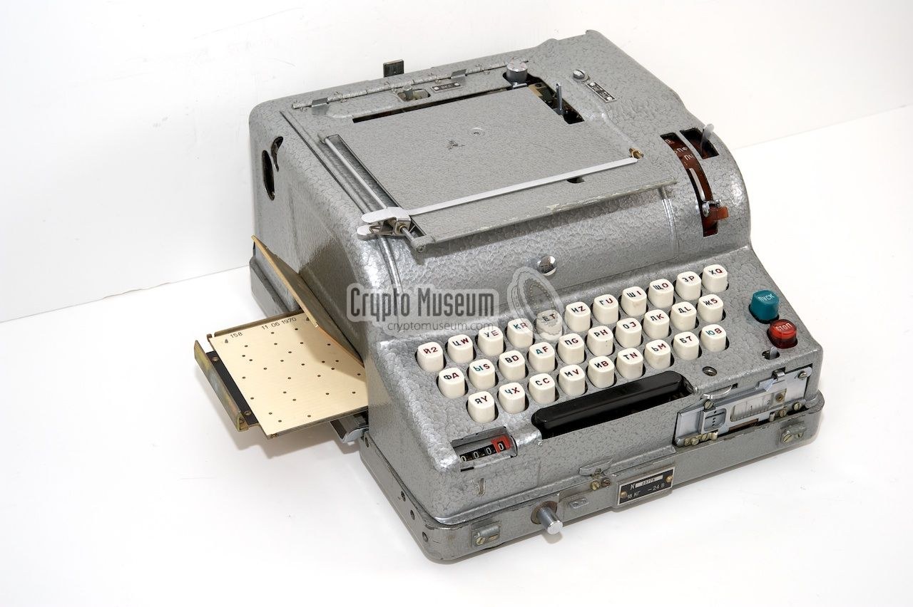
Volume 3 followed the current through the drum of ten wheels. This volume covers everything around the drum, in the order the current meets it: the keyboard and its fixed wiring, the card reader with the day’s punched key card, the reflector, the mode switch, and on the way out the encoder, print head and tape punch. It also covers what the later M-125-3 added, a number shift and a numbers-only mode in which twenty of the thirty lines are looped back on themselves. The volume ends with the power supply, which was designed so that the mains lead would not reveal what was being printed.
The sources are those of Volume 3: Reuvers and Simons’s Fialka M-125 Reference Manual 2.0 (section numbers below are its own), Crypto Museum’s published wiring tables, and the 1978 East German operating manual, A 040/1/321, in its English translation (Crypto Museum; Library copy). All worked examples come from the unit’s simulator, 03-outputs/tools/fialka_sim.py, with the demonstration key of Volumes 3 and 10.
4.2 The Keyboard
The M-125’s keyboard has thirty keys in three rows, eleven, ten and nine, and a space bar. Its key tops carry two alphabets: a Cyrillic letter, the same on every machine, and a Latin letter or figure, different from country to country (Volume 5 covers the national layouts). A switch on top of the M-125 marked РУС / ЛАТ selects which half of the print head is used. The M-125-3’s square keys carry up to four characters each (Reference Manual 1.4.2, 3.2).
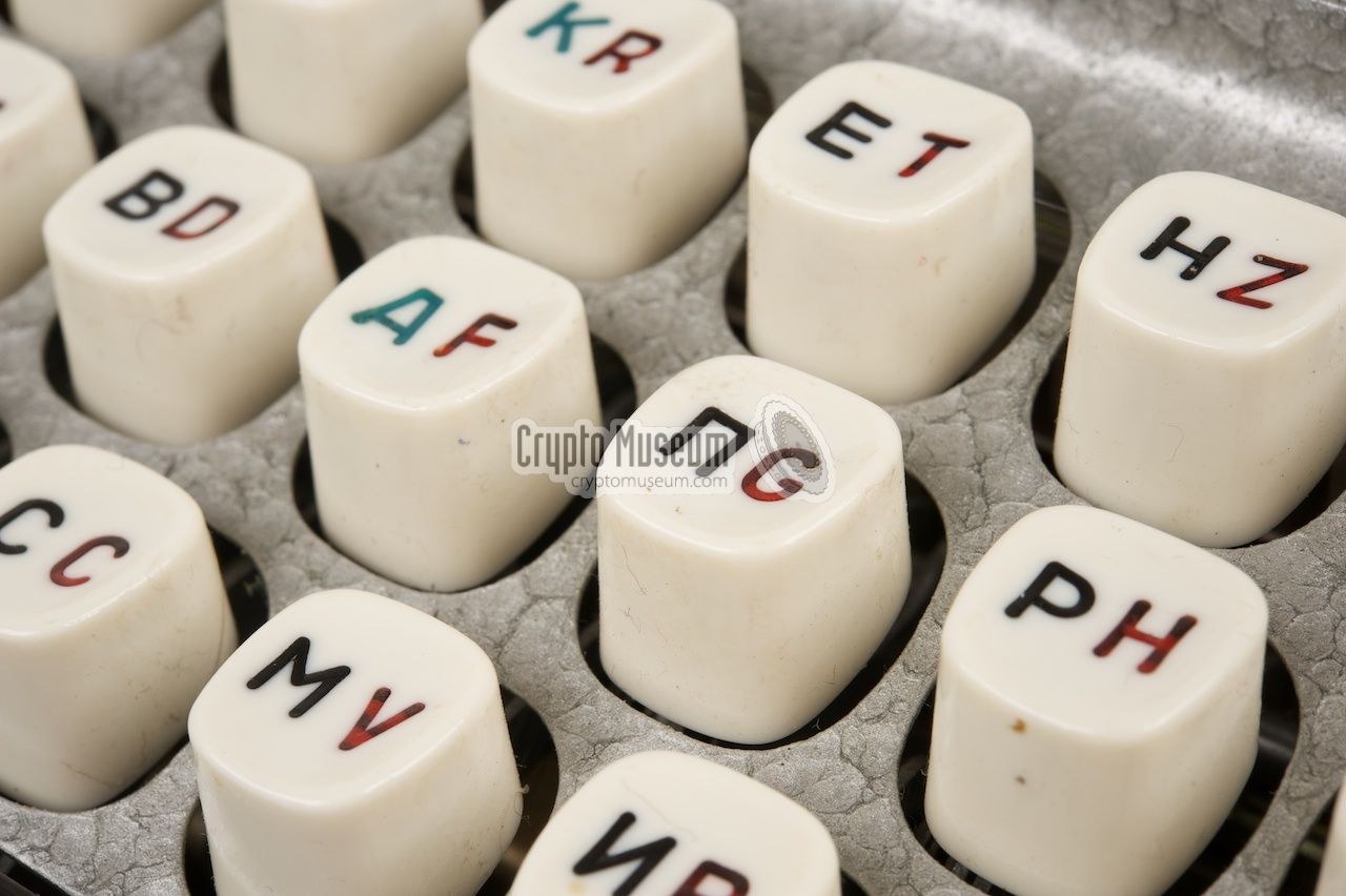
Under the keys is a row of 31 change-over switches, the switch array, one per key and one for the space bar, arranged in the order of the thirty contacts (А Б В … Я Й). Which switch a key closes depends on where the key sits, not on what is printed on it. So a Polish machine’s F key and a Russian machine’s А key close the same switch and send the same current. Each switch works like an Enigma key contact. Pressing it makes one contact, which sends the outgoing current towards the drum, and breaks another. When the current returns from the drum on a different line, it passes through the unpressed key’s normally closed contact on its way to be printed. The switches for Й and for the space bar move together and are routed through the mode switch, so only one of them is live in any mode. When coding, the space bar sends Й; when decoding, a Й coming back is printed as a space (Reference Manual 4.4).
The keyboard does more than close switches. Its “complex mechanical maze of metal pawls, arms, levers, springs and notches” locks every other key while one is down. It releases the key once the letter has been processed and blocks keys that are not allowed in the current mode. It also translates each key, mechanically, into a five-bit code, through five switches in a small box under the keyboard (Reference Manual 4.4, 4.4.3). That code is the plaintext letter in teleprinter form. It is used when the machine prints plain text, and in one special case, described under the reflector below, when it enciphers. The tape reader at the right of the keyboard drives the same mechanism, so a punched tape played back has exactly the effect of typing (Reference Manual 4.4.5).
4.2.1 Fixed Wiring
Between the keyboard and the card reader, and again between the card reader and the entry disc, the wires do not run straight. Crypto Museum traced both scrambles. The keyboard’s switch for contact 1 (А) goes to card-reader input 17, contact 2 to input 25, contact 3 to input 30, and so on through all thirty (Reference Manual 4.6; Crypto Museum, “Fialka wiring”). These wirings were identical on all known machines and never changed. Once known they add no secret, but they do ensure that a key card is not simply a table of which letter becomes which. In the F trace of Volume 3, the keyboard wiring took contact 1 to 17 and the entry disc took 6 to 16.
4.3 The Card Reader
On the left side of the machine, under a shiny metal bracket, is a drawer. Pulled out, it takes a single sheet of thin card punched with thirty holes. Pushed home, it presses thirty sprung contacts against the card, and each contact drops into the hole in its row (Reference Manual 3.6, 4.6). The reader is marked KC 30 × 30. Its German name in the East German manual, Kommutator, describes it better: it is a switchboard of thirty inputs and thirty outputs, and the card decides which input is joined to which output.
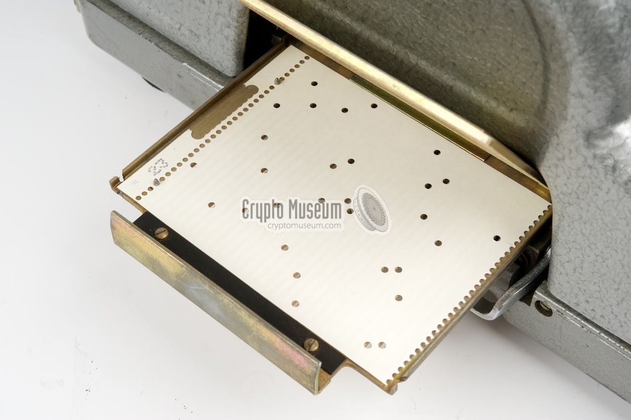
Think of the card as a grid of thirty columns and thirty rows. The columns are the inputs, the lines from the keyboard; the rows are the outputs, the lines to the entry disc. The card has exactly one hole in each column and exactly one in each row. “Each Key Card … contains 30 perforations, of which each row and each column has only one,” as the 1978 manual puts it (A 040/1/321, section 2.2.3). A hole at column c, row r joins input c to output r. A card with two holes in one row would short two lines together. A drawer with no card at all shorts all thirty, so the reader must always hold either a card or the metal test triangle. The triangle forces the identity, input 1 to output 1, 2 to 2 and so on, and was used for testing and repair (Reference Manual 4.6).
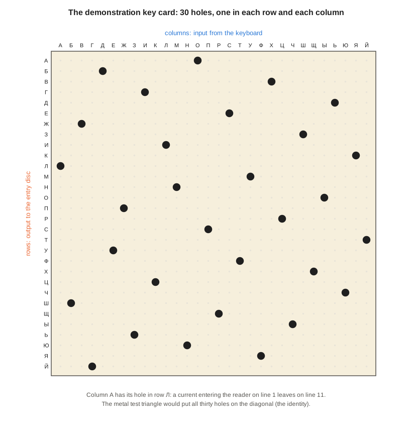
The card is the Fialka’s replacement for Enigma’s plugboard, and it is a far stronger one. An Enigma plugboard with ten cables swapped twenty letters in pairs and left six alone, about 1.5 × 10¹⁴ possibilities. A Fialka card can be any of the 30! ≈ 2.65 × 10³² permutations of thirty lines. It need not swap in pairs: in the demonstration card, input 1 goes to 11, but input 11 goes to 9. A plugboard was set up cable by cable and could be set wrongly. A card was dropped into a drawer, and an operator could not easily get it wrong. Volume 10 counts the whole key space.
The cards were made in the Soviet Union for each country, a year at a time, and issued sewn together in a stack. Each morning the operator tore off the day’s card at the lower perforation and put it in the drawer. Reuvers and Simons note that the cards were thin enough to tear after a few openings of the drawer (Reference Manual 3.6). In the East German system, a month’s Daily Key Package held 31 daily key tables and 31 punched cards numbered 1 to 31, so the number on the card was the day of the month (A 040/1/321, section 2.2.3). Volume 6 describes the key packages and their handling.
4.4 The Reflector
At the left end of the drum, the current meets the reflector, a fixed disc of thirty contacts that sends it back into the wheels. Like Enigma’s reflector, it wires most of its contacts in pairs. Unlike Enigma’s, it does not wire all of them that way (Reference Manual 4.9, 4.10; Crypto Museum, “Magic circuit”). Its thirty contacts are used in three ways:
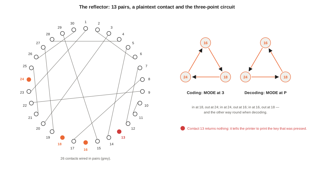
- Twenty-six contacts are wired in thirteen pairs: 1 with 23, 2 with 6, 3 with 20, and so on. A current arriving at either contact of a pair leaves by the other.
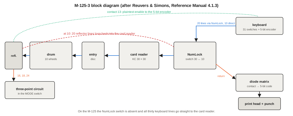
- Contact 13 is not wired to any other contact. A current arriving there goes to the plaintext enable line of the keyboard’s mechanical five-bit encoder. The printer then prints the code of the key that was pressed instead of anything coming back from the drum. That letter has been enciphered as itself.
- Contacts 16, 18 and 24 go to a small transistor circuit, the three-point circuit (German Dreipunktschaltung), which Crypto Museum nicknamed the magic circuit when they first met it in 2005. A current entering the reflector at 18 leaves at 24; one entering at 24 leaves at 16; one entering at 16 leaves at 18. The three contacts are joined in a triangle with a direction.
4.4.1 Why the Triangle
A reflector that pairs every contact cannot send a letter back to itself. The current would have to leave on the same contact it arrived on. On the Enigma this was the flaw that let codebreakers slide a probable word along a message and reject every position where any letter stood over itself. The Fialka’s designers removed it by isolating contact 13. But that left twenty-nine contacts, and an odd number cannot be paired. Pairing all but three and joining the three in a one-way triangle solves the problem.
The cost is that the machine is no longer its own inverse. Enigma deciphered with exactly the settings it enciphered with. On the Fialka, a current that goes 18 → 24 when coding must go 24 → 18 when decoding. The mode switch therefore swaps two of the three wires when it is set to decoding, which reverses the triangle. This is why the circuit lives inside the large red Bakelite housing of the mode switch to the right of the drum (Reference Manual 4.5, 4.9).
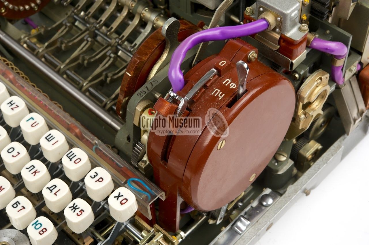
The circuit itself is three similar transistor stages in a ring, each feeding the next through a diode, the last feeding back to the first. Because the machine works in negative logic, a line is active when it is pulled down to 0 V. Pulling one of the three lines low makes the next line low and the third high, so “a low on line n will result in a low on line n + 1 and a high on the remaining line” (Crypto Museum, “Magic circuit”). Early machines used large Soviet P701A transistors on a Bakelite carrier; later ones used smaller 2T603A transistors on epoxy board. Transistors had only just appeared when the M-125 was designed, a point Reuvers and Simons note with some admiration. A spare diode on the same board connects reflector contact 13 to the plaintext enable line.
4.4.2 What the Reflector Does to the Cipher
Three consequences can be measured on the simulator.
A letter can encipher to itself, about once in thirty. With the demonstration key, sixty А’s typed in a row come out with А at positions 12, 20, 26, 53 and 56, and in 3,000 key-presses 98 came back as themselves, close to the expected 100. In Volume 10’s worked message, three letters of 89 are enciphered as themselves. Enigma’s rule that “no letter is its own cipher” does not hold, and Volume 10 shows what that does to an attack that relies on it.
Coding and decoding are different. With the mode switch left at coding, the worked message of Volume 10 “deciphers” with 10 of its 90 letters wrong. Every letter whose path happens to touch the triangle comes out wrong, and the rest come out right. A receiving operator who forgot the switch would see a recognisable but corrupted text, which is a useful diagnostic. In decoding mode it comes out perfectly.
The plaintext contact is a property of the path, not of the letter. Which key is enciphered as itself depends on where the wheels and card happen to put contact 13, so it changes at every key-press. When deciphering, the same path leads to contact 13 again, and the printer prints the cipher letter as typed, which is the plaintext. The scheme is consistent.
4.5 The Mode Switch
The lever on the red housing has three positions: О for plain text, Р for decoding and З for coding. The English translation of the East German manual gives them as K, D and C, from the German Klartext, Dechiffrieren and Chiffrieren. In plain-text mode the drum is bypassed, and the machine is an ordinary teleprinter that prints and punches what is typed, using the mechanical five-bit encoder. Operators typed the clear parts of a message this way: the system indicator group and the identification group at the head of the tape, the service group at the end (Volume 10). On the M-125-3 the wheels do not move in plain-text mode, so clear text can be typed without disturbing the message setting (Reference Manual 1.4.2). The manual lists this among the M-125-3’s differences from the M-125.
4.6 Printer, Punch and the Five-Bit Code
The returning current, having passed back through the drum, card reader and keyboard wiring, arrives on one of thirty lines. A diode matrix under the drum converts it into a five-bit pattern. The pattern drives five solenoids in the printer and, if it is switched on, five punch magnets (Reference Manual 4.11, 4.12). The code is not the international teleprinter (Baudot) code but the Fialka’s own, with thirty letters plus a space and a blank. The same code is used by the Soviet M-105 one-time-tape machine (Volume 2). The keyboard’s mechanical encoder produces the same code for the plaintext letter, and the plaintext enable line chooses between the two.
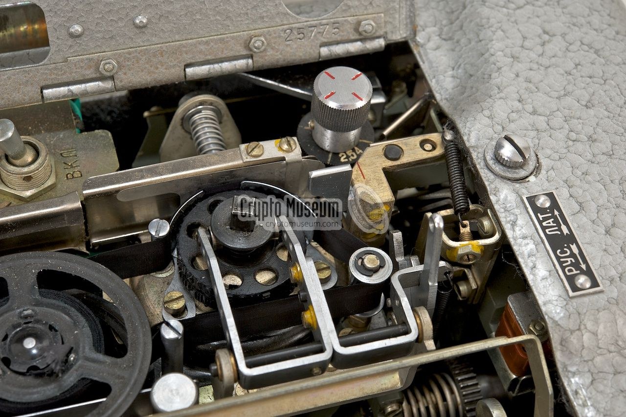
The print head is a small drum spun by the motor and stopped when the right character faces the paper, at which point a hammer strikes it through the ink ribbon. The ribbon reverses automatically at the end of its run, like a typewriter’s. Each row of the head has 34 positions, the thirty characters and a few extras. One extra is an asterisk, printed whenever a letter fails to encipher, for example when a dirty wheel contact breaks the circuit. A tape sprinkled with asterisks meant the contacts needed cleaning. Another is the equals sign, which appears when the head has been put on its shaft the wrong way round (Reference Manual 3.4.6, 3.4.9). The M-125 has one combined head, Cyrillic on the lower row and Latin on the upper, chosen by the РУС / ЛАТ switch. The M-125-3 uses a separate head for each script, each with two rows: the standard characters below and figures and punctuation above. A lifter raises the head to its upper row when needed (Reference Manual 3.4.4–3.4.8).
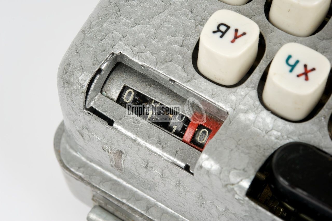
The machine prints on one of two tapes. Standard 17.5 mm five-hole teleprinter tape runs from the right through the punch and past the print head, so the punched code and the printed letter are about 75 mm apart on the same tape. 10 mm gummed tape, as used for telegrams, bypasses the punch and is printed only; it was stuck onto a message form (Reference Manual 3.4.1). A lever on the right side groups the output in fives automatically. A four-digit letter counter to the left of the space bar counts in groups: its last digit counts to five, and the other three count groups of five (Reference Manual 2.10).
The 1978 manual gives the machine’s speed as at most 500 characters a minute from the keyboard and 455 from tape, about eight a second. It gives the error rate as 2 × 10⁻⁵ (A 040/1/321, section 2.1.2). With the punch on, an enciphered message came off the machine ready for a teleprinter line or a radio transmitter. The machine could also re-read a punched tape to print it, copy it or encipher it.
4.7 The M-125-3: Mixed Text and Numbers Only
The M-125-3 kept the M-125’s cipher unchanged. A message enciphered on one deciphers on the other with the same wheels and key. What it added was a way to send figures and punctuation, and a separate mode for numeric code. A three-position TEXT MODE lever behind the printer selects Б (буквы, letters), С (смешанный, mixed) or Ц (цифры, numbers). A lever at the lower left, marked 30 ↔ 10, sets how many lines are live (Reference Manual 1.5.2, 3.2.8–3.2.10).
4.7.1 Mixed Mode
In letters mode the M-125-3 is an M-125. In mixed mode it behaves like a teleprinter with a figure shift. Two keys are given up to shift keys: one moves the print head to its upper row of figures and punctuation, and the other moves it back to letters. The letters on those two keys, Ф and Ж, move to the upper row. The shift keys are enciphered like any other key and step the wheels. If they were not, the receiver would have no way of knowing that the shift had changed. The cipher text is printed in letters throughout, and only the deciphered plaintext uses both rows. On the simulator, with a Cyrillic head and the demonstration key, the plaintext ВЫСОТА 250 МЕТРОВ (“altitude 250 metres”), typed with a figure shift before 250 and a letter shift after, is nineteen key-presses and enciphers to nineteen letters:
ИЙУШЛ ВОЧЯЯ ЩХМЮР ОПБЫ
Deciphered in mixed mode, it prints ВЫСОТА 250 МЕТРОВ again, the shift keys silently moving the head. This behaviour, with the cipher the same as in letters mode and the shift keys enciphered but not printed, was recorded from Chernov’s simulator by the Lumenman project (github.com/Lumenman/FIALKA). It is reproduced by the simulator’s self-test. The Reference Manual describes the shift keys but not how the cipher text is printed, so this detail rests on the simulator recording.
4.7.2 Numbers Only: the 30 ↔ 10 Switch
The numbers-only mode is the M-125-3’s most unusual feature. It was meant for super-encipherment: messages already turned into figures by a code book, which needed enciphering again without being turned back into letters. With the TEXT MODE lever at Ц and the 30 ↔ 10 switch at 10, only the ten coloured figure keys can be pressed, and the Russian print head is required. A figure must come out as a figure, but the drum and reflector have thirty contacts. The solution is to make the current go round again. In the 10 position the switch reroutes twenty of the thirty lines. Only ten reflector contacts remain live: the four “magic” contacts and three fixed pairs. The twenty others are led back into the card reader on the contacts of the twenty dead keys. A current that reaches the reflector on a dead contact is sent into the drum again, and again, until it reaches a live one. On the way back it loops the same way until it arrives at one of the ten figure keys (Reference Manual 4.1.3, 4.8).
On the simulator, with the demonstration key and the switch at 10, the three groups
12345 67890 11111
encipher to
99820 29816 76686
and decipher back to the figures. The groups of five ones show that a repeated figure enciphers to a changing one, as any letter does. The looping tables are those Reuvers and Simons traced and CrypTool 2 implemented, and the simulator reproduces ten published test strings in this mode (Volume 9). The 1978 manual had a rule for converting figures into letters for the message key: a numeric message used digits for its identification groups, and these were converted with the table 1 → А, 2 → Б … 0 → К before being set on the wheels (A 040/1/321, section 7.3.3).
4.8 Power and the Eavesdropper
The Fialka runs on a single 24 V DC supply. It could come from the battery of a truck or armoured vehicle, or from the issued power unit. The unit takes mains from 100 to 250 V at 50 or 400 Hz, or 24 V DC, through a multi-tap transformer, and gives 24 V out. The 1978 manual quotes 50 VA consumption. It gives the machine at its working position as 465 × 380 × 350 mm and 16 kg, with the power unit a further 6.8 kg (A 040/1/321, section 2.1.2). Inside the machine, a power module on the left side filters both lines, fuses the motor at 5 A and the rest of the machine at 3 A, and carries a wire-wound potentiometer that sets the speed of the 24 V motor driving the cams, combs and printer (Reference Manual 4.3).
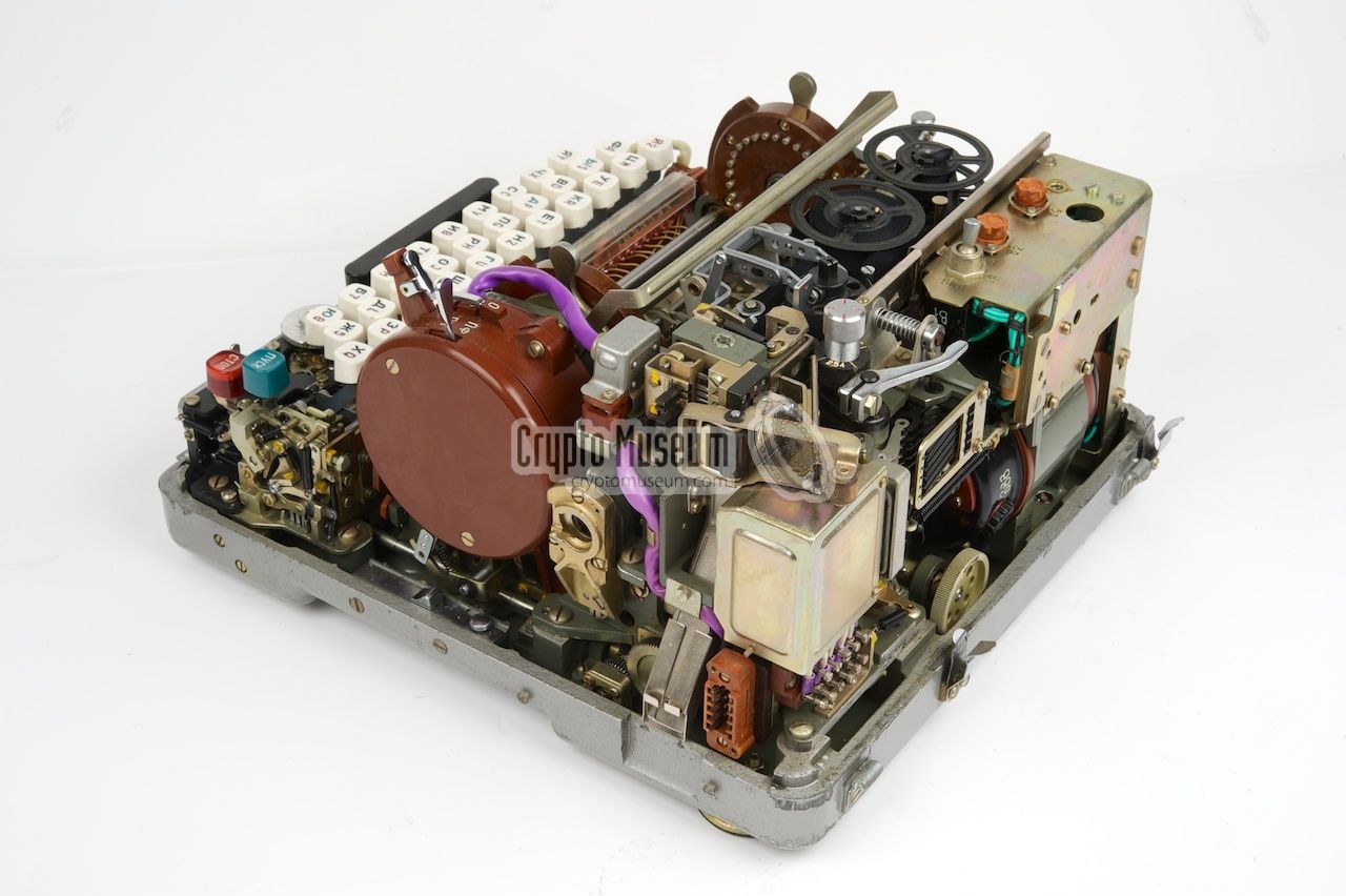
Power was also a security problem. Reuvers and Simons explain why (Reference Manual 4.2.4–4.2.5). Each printed letter fires between one and five solenoids, according to the number of ones in its five-bit code, and draws current accordingly. A listener with a probe on the mains could, in principle, follow those surges and learn something about the printed text. The Soviet answer was a special stabilised supply, often found with Polish machines; Crypto Museum lists it as the BPK-125 TEMPEST supply. It took the five-bit output of the machine and switched in one dummy load for each solenoid not fired, so the supply always saw the load of five. The mechanics were treated the same way: every key-press runs the same cam cycle, so to an ear or a microphone every letter sounds alike. Volume 5 describes the power supplies, and Volume 7 asks what eavesdropping on cipher machines achieved in practice.
4.9 One Key-Press, End to End
With the two volumes together, the whole cycle can be set out. A key-press:
- locks every other key and starts the motor-driven cycle; the keyboard’s mechanical encoder sets up the five-bit code of the plaintext letter;
- closes one switch of the array; a pulse switch then pulls the common rail to 0 V, sending the current out through the keyboard wiring;
- passes the card, the entry disc and the ten wheels (Volume 3), with the +3 offset at each end of the drum;
- meets the reflector: a pair sends it back; the triangle turns it one way or the other according to the mode; contact 13 stops it and enables the plaintext code;
- returns through the wheels, the entry disc, the card and the keyboard wiring to the diode matrix, which converts it into five bits, unless contact 13 has substituted the plaintext’s own five bits;
- fires the print head and, if selected, the punch; the counter advances;
- drives the transport combs, which step the wheels according to the blocking pins (Volume 3), and releases the keyboard.
At eight such cycles a second, a skilled operator could encipher a three-hundred-group message, the length at which the East German rules required a message to be split, in under four minutes of typing (A 040/1/321, section 3.2). Volume 6 explains what surrounded that typing: the key packages, the indicator groups and the rules for when a message had to be split.
Sources
- Paul Reuvers & Marc Simons, Fialka M-125 Reference Manual, version 2.0, Crypto Museum (sections 1.4–1.5, 2.10, 3.2, 3.4–3.7 and 4.1–4.12): PDF (Library copy).
- Crypto Museum, “Magic circuit”: cryptomuseum.com/crypto/fialka/magic.htm; “Fialka wiring” (keyboard, card reader, entry disc and reflector tables): cryptomuseum.com/crypto/fialka/wiring.htm; “M-125”: cryptomuseum.com/crypto/fialka/m125/index.htm.
- Nationale Volksarmee, A 040/1/321 — System M-125 — Operations manual, 1978, English translation by “JMcC” (sections 2.1.2, 2.2.3, 3.2, 7.3.3): PDF (Library copy).
- Lumenman, FIALKA (emulator of the M-125-3 with mixed-mode test strings recorded from Chernov’s simulator), MIT licence, 2026: github.com/Lumenman/FIALKA.
- Worked examples:
03-outputs/tools/fialka_sim.py(this series).
Next — Volume 5: Models and Variants. The M-125 and the M-125-3 side by side and how to tell them apart; the national versions for the Soviet Union, Poland, Czechoslovakia, East Germany and Hungary, with their keyboards and print heads; the two generations of wheels and the series codes stamped on them; the standard and TEMPEST power supplies; and what came in the box.
Comments (0)