Fialka · Volume 3
Fialka — Volume 3 — How It Works I — Ten Rotors, Alternate Stepping and the Blocking Pins
The drum of ten thirty-contact wheels, the order of the Cyrillic contacts, the path of one current wire by wire, the arithmetic of position, ring and core, the two stepping chains that turn in opposite directions, the blocking pins that hold them back, and the 1978 wheels whose wiring could be lifted out and turned over
3.1 About This Volume
Volumes 1 and 2 introduced the M-125 and traced where it came from. This volume and the next take the machine apart. This one covers the drum: the ten wheels, the contacts that carry the current through them, and the mechanism that moves them after every letter. Volume 4 covers everything around the drum: the punched-card reader that stands in for Enigma’s plugboard, the reflector with its three-transistor “magic circuit”, the keyboard, the printer, the tape punch and the power supply.
The drum is where the Fialka differs most from the Enigma. The two machines share a basic idea: a current passes through a stack of wired wheels, bounces off a reflector and comes back by another route. Almost every detail of that idea was changed, though. There are ten wheels instead of three or four, thirty contacts instead of twenty-six, and two independent stepping chains that turn in opposite directions. The wheels move irregularly, governed by pins on their own rims. From 1978 a new wheel set let the operator take the wiring out of each wheel, turn it over, rotate it and put it in a different wheel body.
The primary technical source is Paul Reuvers and Marc Simons’s Fialka M-125 Reference Manual (version 2.0), the result of reverse-engineering the machine from scratch at the Crypto Museum from 2005 onwards (Crypto Museum; the PDF has been free since January 2021). Section numbers below are that manual’s. The wheel wirings and pin positions are those Crypto Museum measured on surviving wheels and published for simulator authors (Crypto Museum, “Fialka wiring”).
Every worked example comes from the unit’s simulator, 03-outputs/tools/fialka_sim.py. It is built from the Crypto Museum tables and reproduces 35 published test encipherments made with Vyacheslav Chernov’s independent Fialka simulator, plus three more recorded from the same program by a second project; Volume 9 describes the tests. The examples use the series’s demonstration key, an adjustable-wheel key for a Czechoslovak 6K wheel set invented for this purpose. It is not a historical key, but the wheels are real: the 6K wirings were traced from wheels that came out of the former Czechoslovakia around 2005.
3.2 The Drum on the Bench
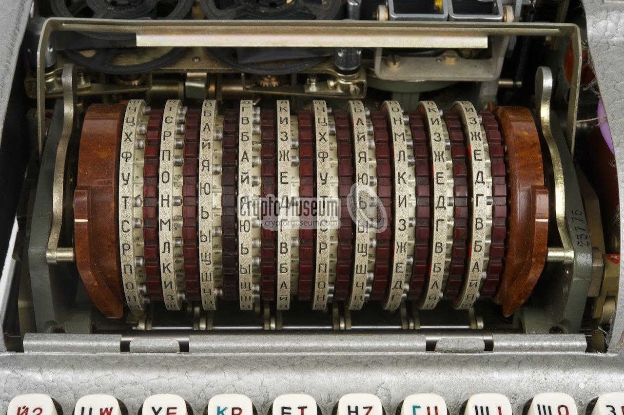
Lifting the M-125’s lid exposes the drum: ten wheels side by side on a horizontal spindle, flanked by two fixed discs. On the left is the reflector, which cannot be removed. On the right is the entry disc, which brings in the thirty wires from the card reader. Across the front of the drum runs a hinged metal ruler. The letter on each wheel just above the ruler is that wheel’s current position, and setting a message key means turning each wheel by hand until the right letter shows there.
To take the wheels out, the operator raises the ruler, presses the drum down, releases two levers, slides the two static discs aside and lifts the whole drum out on its spindle. A retaining clip at the right-hand end holds the wheels on the spindle (Reference Manual 3.3.2). Each wheel is marked with one of the first ten letters of the Cyrillic alphabet, А Б В Г Д Е Ж З И К. A machine had one of each, and the daily key said in which order they went on the spindle. Crypto Museum numbers them 1 to 10 for convenience, which this series also does. Machines were issued with two complete sets, an operational set lettered in black and a spare set lettered in red, each kept in its own aluminium can (Crypto Museum, M-125).
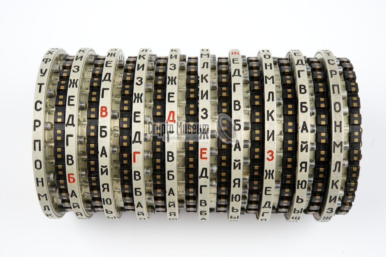
Each wheel is a sandwich of Bakelite (later plastic) and metal. The right-hand face carries thirty spring-loaded contacts; the left-hand face carries thirty flat contacts. Inside, thirty wires join each spring contact to a different flat contact. Around the rim run the letter band, a ring of thirty notches that the stepping mechanism engages, and the advance blocking pins: short steel pegs fitted at some of the thirty positions and missing at the others. The pins are the subject of the second half of this volume.
3.3 Thirty Contacts
Every part of the signal path has thirty contacts, and all of them are numbered in the same order, the order of the letters engraved around each wheel:
Table 1 — Every part of the signal path has thirty contacts, and all of them are numbered in the same order, the order of the letters engraved around each wheel
| Contact | 1 | 2 | 3 | 4 | 5 | 6 | 7 | 8 | 9 | 10 | 11 | 12 | 13 | 14 | 15 |
|---|---|---|---|---|---|---|---|---|---|---|---|---|---|---|---|
| Letter | А | Б | В | Г | Д | Е | Ж | З | И | К | Л | М | Н | О | П |
| Contact | 16 | 17 | 18 | 19 | 20 | 21 | 22 | 23 | 24 | 25 | 26 | 27 | 28 | 29 | 30 |
| Letter | Р | С | Т | У | Ф | Х | Ц | Ч | Ш | Щ | Ы | Ь | Ю | Я | Й |
The Russian alphabet has 33 letters, so three had to go. Ё, Ъ and Э are missing (Ъ and Э came back on the upper row of the later M-125-3’s print head; Volume 4). The order is the alphabet’s except that Й, which normally follows И, has been moved to the end. Reuvers and Simons point out that this sequence is not the keyboard’s and should be read as a numbering of contacts rather than as an alphabet (Reference Manual 3.3.1). Contact 30, Й, is special: the space bar is wired in parallel with it, so a space typed into a message is enciphered as Й and a Й in a deciphered text is printed as a space.
The direction of the current fixes the vocabulary. Current enters a wheel at its right-hand, spring-contact face, called the input, and leaves at its left-hand, flat face, the output. A wheel’s wiring is therefore written as a list: for each input contact 1 to 30, the output contact it is joined to. That is how Crypto Museum publishes it. Wheel А of the Czechoslovak 6K set, for example, begins 13, 22, 08, 18 …: its input 1 is wired to output 13, input 2 to output 22, and so on (Crypto Museum, “Fialka wiring”).
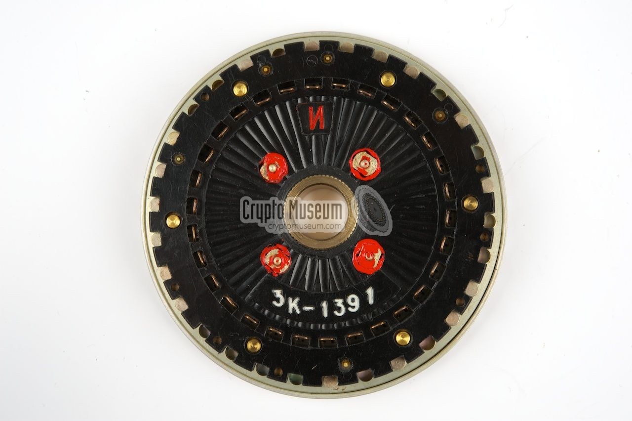
The wiring was not the same everywhere. All the wheels were made, wired and distributed in the Soviet Union, but each Warsaw Pact country received its own series, identified by a prefix to the serial number on every wheel. Crypto Museum has measured four: 68 for the Soviet Union (traced in 2017, when two original Russian machines turned up with their wheels; the 2009 Reference Manual had given the Russian prefix as 1K, and the question is not settled, as Volume 5 explains), 3K for Poland (data from David Hamer and Tom Perera), 5K, probably Hungary, and 6K for Czechoslovakia. The East German 4K set is known only from a photograph in a recovered manual, and a 7K set of unknown use was found at a German flea market in 2022 (Crypto Museum). The pin positions differ between series as well as the wiring. Volume 5 discusses the national versions and Volume 6 the “common” sets held back for wartime traffic between allies.
3.4 The Path of a Current
Pressing a key closes one of thirty switches under the keyboard. The current then follows a fixed route (Reference Manual 3.7, “Sequence of Events”):
- from the keyboard to the card reader, through a fixed wiring that scrambles the keyboard’s order;
- through the punched key card, a substitution that changed every day;
- from the card reader to the entry disc, through another fixed scramble;
- through the ten wheels from right to left, wheel 10 first and wheel 1 last;
- into the reflector, which sends it back out on a different contact;
- through the ten wheels again, left to right;
- back through the entry disc, the card reader and the keyboard wiring in reverse, to the printer.
Only after the letter has been printed do the wheels move.
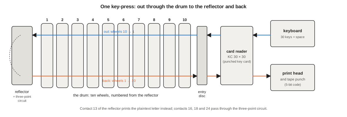
Two features of this route matter for everything that follows. First, the wheels are numbered from the left: wheel 1 sits next to the reflector and wheel 10 next to the entry disc. The 1978 East German operating manual uses the same convention when it tells the operator to set “the first rotor (counting from the left)” to the first letter of the message key (NVA A 040/1/321, section 7.3.2; English translation; Library copy). Second, the entry disc’s contact 1 does not meet a wheel’s contact 1. It meets the contact three places on from the letter showing above the ruler. Reuvers and Simons found this offset when they checked their reconstruction against a working machine and list it explicitly: “+3 (difference between contact 1 of the entry-disc and letter above the ruler)”. The same offset applies at the reflector end (Reference Manual 3.7).
The reflector is described in Volume 4. For this volume it is enough to know that it joins most of its thirty contacts in pairs, as Enigma’s did, with two exceptions. One contact makes the printer print the letter that was typed, so that a letter can encipher to itself. Three others are joined by a transistor circuit that sends the current round a triangle, so that deciphering needs a different mode from enciphering.
3.5 Inside One Wheel
A fixed wheel has one setting, its position. An adjustable wheel of the 1978 set has three: its position (the letter above the ruler), its ring setting (how far the ring carrying the pins and letters has been turned against the wheel body) and its core setting (how far the removable wiring core has been turned inside the body). Reuvers and Simons give the arithmetic for a current passing through one wheel from right to left (Reference Manual 3.7):
- add the wheel’s current position;
- add the ring setting;
- subtract the core setting;
- look up the core’s wiring;
- add the core setting;
- subtract the ring setting;
- subtract the position.
All arithmetic is modulo 30, counting positions from zero (А = 0). A current going the other way, left to right, uses the inverse of the wiring at step 4. If the core has been turned over, the mirror image of the wiring is used instead, as described later in this volume.
The demonstration key shows the arithmetic in practice. Wheel slot 10, next to the entry disc, holds the wheel body Д with the core Ж in it, side 1 out. Its ring is set at И (9), its core at Ч (23), and its position is Б (2). A current arrives at its input contact 19. In the 1-to-30 numbering, the three settings add 2 − 1 = 1, 9 − 1 = 8 and subtract 23 − 1 = 22:
19 + 1 + 8 − 22 = 6.
Core Ж of the 6K set wires its contact 6 to contact 8. Unwinding the settings:
8 − 1 − 8 + 22 = 21.
The current leaves wheel 10 on contact 21 and enters wheel 9 there. The simulator’s trace below shows the same step.
Two things follow from this arithmetic. First, the position and the ring setting enter only as their sum. Turning a wheel five places on and its ring five places back gives exactly the same cipher, and the simulator’s self-test checks this. The ring setting matters because the position is visible and the ring setting is not. A message key, written down or sent as an indicator, tells an eavesdropper the positions; without the day’s ring settings it does not tell them where the wirings actually stand. Enigma’s ring setting served the same purpose. Second, the core setting moves the wiring without moving the pins, while the ring setting moves the pins. Between them, the stepping pattern and the wiring can be set independently.
3.6 One Letter, Wire by Wire
The demonstration key’s message setting puts the ten wheels at positions 16 04 27 09 21 13 30 06 18 02 (Р Г Ь И Х Н Й Е Т Б), counted from the reflector. The key-top F, on a Czechoslovak machine with the Latin print head, is wired to contact 1 (А). The simulator traces it:
Table 2 — The demonstration key's message setting puts the ten wheels at positions 16 04 27 09 21 13 30 06 18 02 (Р Г Ь И Х Н Й Е Т Б), counted from the reflector. The key-top F, on a Czechoslovak machine with the Latin print head, is wired to contact 1 (А). The simulator traces it
| Stage | In | Out |
|---|---|---|
| keyboard wiring | 1 | 17 |
| key card | 17 | 6 |
| entry disc | 6 | 16 |
| +3 to the ruler | 16 | 19 |
| wheels 10 → 1 | 19 | 21, 19, 12, 8, 3, 1, 17, 17, 12, 7 |
| −3 to the reflector | 7 | 4 |
| reflector (a plain pair) | 4 | 28 |
| +3 to the ruler | 28 | 1 |
| wheels 1 → 10 | 1 | 14, 4, 2, 3, 11, 29, 6, 9, 18, 17 |
| −3 to the entry disc | 17 | 14 |
| entry disc, backwards | 14 | 2 |
| key card, backwards | 2 | 5 |
| keyboard wiring, backwards | 5 | 22 |
Contact 22 is the key-top W, so the machine prints W. The current crossed twenty wheel wirings, the key card twice and the fixed wirings four times, and it touched the reflector at an ordinary pair. Had it arrived at reflector contact 13, the printer would have printed F itself. Had it arrived at 16, 18 or 24, the three-point circuit would have redirected it. Volume 4 follows both cases.
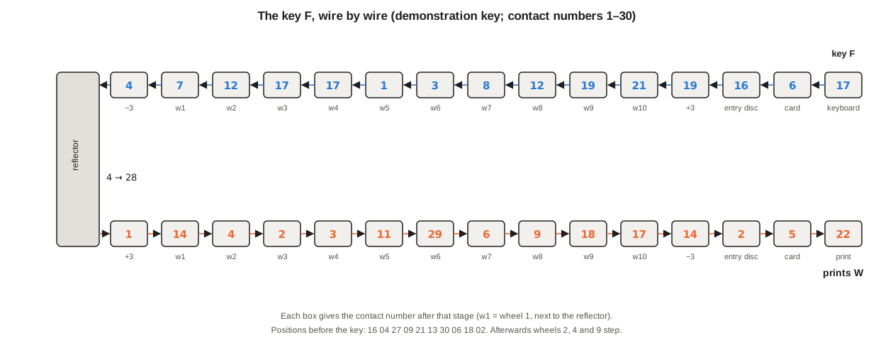
Only now do the wheels step. On this key-press, wheels 2, 4 and 9 move; the other seven stay where they are. Explaining why is the business of the rest of this volume.
3.7 Alternate Stepping
An Enigma moved like a mileage counter. The right-hand wheel stepped on every key, and a notch on it occasionally carried the next wheel on by one. The Fialka’s ten wheels are divided into two independent chains (Reference Manual 3.3.8):
- the even wheels, 2, 4, 6, 8 and 10, which turn away from the operator when seen from above. Wheel 2, next-but-one to the reflector, is the fast wheel. It steps on every key-press, and the carry runs to the right: 2 → 4 → 6 → 8 → 10;
- the odd wheels, 9, 7, 5, 3 and 1, which turn towards the operator. Wheel 9, next-but-one to the entry disc, is the fast wheel. It also steps on every key-press, and the carry runs to the left: 9 → 7 → 5 → 3 → 1.
Adjacent wheels therefore always belong to different chains and turn in opposite directions. A wheel never affects its neighbour, only the wheel two places away. Reuvers and Simons called this alternate stepping.
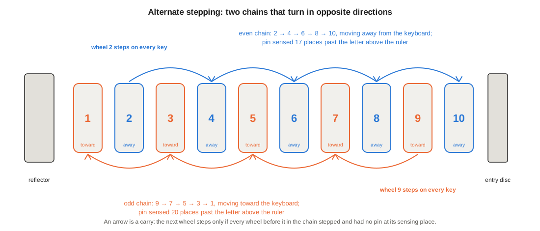
The second difference is the sense of the carry. On an Enigma, a notch on the fast wheel causes the next wheel to step. On the Fialka, every wheel in a chain steps on every key-press unless something stops it, and what stops it is a blocking pin. If the fast wheel has a pin at the sensing position, the next wheel in its chain does not move, and neither does any wheel beyond it. If the fast wheel has no pin there, the second wheel moves, and its own pin decides whether the third moves; and so on down the chain. In the manual’s words: “If an advance blocking pin is present in a certain location on a wheel, all wheels to the right of it, will not be stepped” (Reference Manual 3.3.8, describing the even chain).
The rule in one line: a wheel steps if every earlier wheel in its chain stepped and none of them had a pin at its sensing place. The two fast wheels always step. The last wheel of each chain, 10 and 1, can be blocked but blocks nothing, because nothing follows it.
3.7.1 The Mechanism
The mechanism is a small piece of precision engineering, and its form explains the rule. Underneath the drum, between the entry disc and the reflector, lie two transport combs, one for each chain. On every key-press the motor-driven cam train pushes the two combs apart and back again. Each comb is a row of linked arm segments on a thin axle. Each segment has two fingers. The transport finger engages one of the thirty notches on the rim of its own wheel and pulls the wheel one step as the comb moves. The carry-on finger, set slightly to one side, rides on the rim of the preceding wheel of its chain, the wheel two places away.
If that preceding wheel has a pin at the sensing position, the pin pushes the carry-on finger down. The finger takes its transport finger down with it, out of engagement, so the wheel does not move. Because the transport finger is itself the next segment’s carry-on point, pushing it down also disengages the next wheel, and so on to the end of the chain. The odd comb is mounted upside down relative to the even one, which is why its wheels turn the other way. Above both combs, a row of ten spring-loaded lock-step arms, each ending in a small roller, holds every wheel firmly in one of its thirty positions between steps (Reference Manual 3.3.8). The combs are driven mechanically, so a key-press that moves two wheels sounds the same as one that moves ten. Volume 4 returns to the acoustic security of the design.
3.8 Where the Pins Are Read
A pin is not read at the ruler. The comb sits under the drum, so the pin that matters is a long way round the wheel from the letter the operator sees. For the even chain it is the pin 17 positions on from the letter above the ruler; for the odd chain, whose fingers sit three notches further round, it is 20 positions on. With А above the ruler, an even wheel is blocked by a pin at position 18 (Т) and an odd wheel by a pin at position 21 (Х) (Reference Manual 3.3.6 and 3.3.8). The ring setting moves the pins with the ring, so on an adjustable wheel the sensed position is the position plus the ring setting plus 17 (or 20).
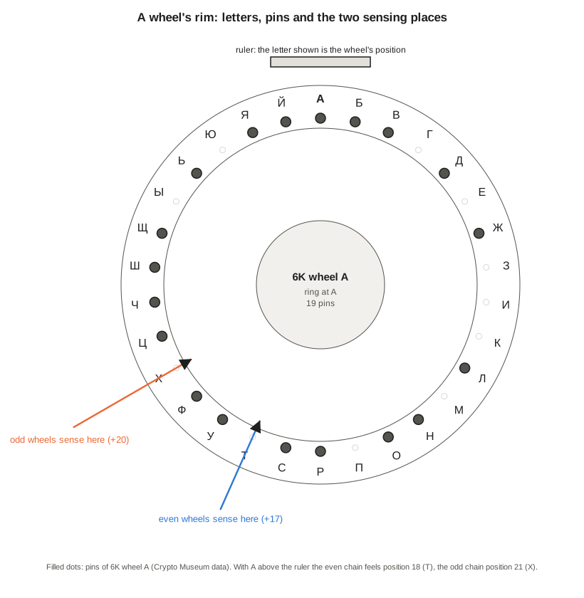
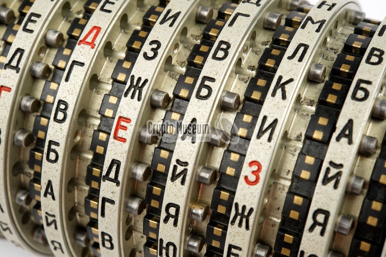
How many pins does a wheel carry? Crypto Museum’s tables give every pin of every measured wheel:
Table 3 — How many pins does a wheel carry? Crypto Museum's tables give every pin of every measured wheel
| Series | Wheel А | Б | В | Г | Д | Е | Ж | З | И | К |
|---|---|---|---|---|---|---|---|---|---|---|
| 68 (USSR) | 17 | 23 | 11 | 19 | 7 | 17 | 13 | 7 | 11 | 11 |
| 3K (Poland) | 13 | 17 | 7 | 23 | 7 | 13 | 23 | 7 | 17 | 13 |
| 5K (Hungary?) | 11 | 7 | 7 | 7 | 11 | 11 | 13 | 19 | 17 | 19 |
| 6K (Czechoslovakia) | 19 | 11 | 7 | 19 | 7 | 17 | 17 | 11 | 7 | 23 |
Every count in every series is one of six numbers: 7, 11, 13, 17, 19 or 23. These are the primes between 7 and 23, and none of them shares a factor with 30. The pattern is too regular to be chance, and the arithmetic suggests a reason. Suppose a fast wheel carries p pins. During one full turn of that wheel, the next wheel in the chain is released 30 − p times, and 30 − p is then also coprime to 30 (23, 19, 17, 13, 11 or 7). After each turn of the faster wheel, the slower one has advanced by an amount that shares no factor with 30, so it passes through all thirty positions before its pattern repeats. Pin counts such as 10 or 15 would cut a wheel’s cycle short. No Soviet document explaining the choice has been published, so this reading is inference. The simulator bears it out for the demonstration key: each chain of five wheels runs 24,300,000 key-presses, exactly 30⁵, before its positions repeat. Antal and Zajac analysed the effect of the blocking pins on the period formally (Cryptologia 39(2), 2015). Volume 10 returns to the period and the key space.
3.9 Thirteen Key-Presses
The demonstration key’s first thirteen key-presses show the pattern. In each row of the table below, the numbers are the positions when the key is pressed, and a shaded cell is a wheel that steps afterwards.
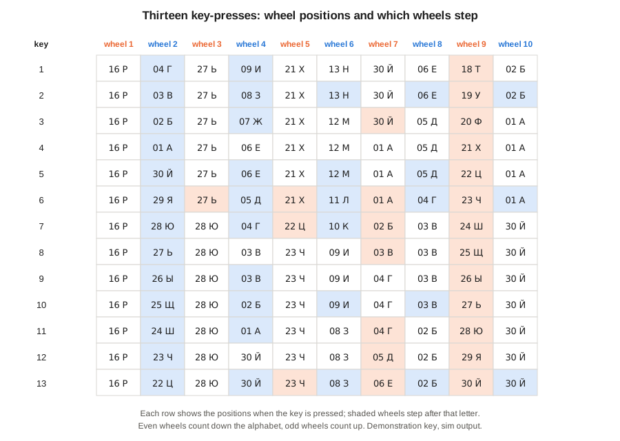
Several features are visible at once. Wheels 2 and 9 move on every row, wheel 2 counting down through Г, В, Б, А, Й, Я … and wheel 9 counting up through Т, У, Ф, Х, Ц …. Wheel 4 moves on most rows, held back only when wheel 2 shows a pin at its sensing place. Wheel 7 moves often; wheel 1 never moves in these thirteen rows. The number of wheels moving varies from two (row 4) to all ten except wheel 1 (row 6). This is quite unlike an Enigma, where the right-hand wheel moves alone on most key-presses.
Over a longer run the averages settle. In 300,000 simulated key-presses with the demonstration key, the share of key-presses on which each wheel stepped was:
Table 4 — Over a longer run the averages settle. In 300,000 simulated key-presses with the demonstration key, the share of key-presses on which each wheel stepped was
| Wheel | 1 | 2 | 3 | 4 | 5 | 6 | 7 | 8 | 9 | 10 |
|---|---|---|---|---|---|---|---|---|---|---|
| Steps per key-press | 0.02 | 1 | 0.10 | 0.77 | 0.23 | 0.28 | 0.63 | 0.22 | 1 | 0.14 |
| Chain | odd | even | odd | even | odd | even | odd | even | odd | even |
On average 4.4 wheels move per key-press. Two always move, and occasionally all ten do. The rates depend on the key: they follow from which wheels are in which slots and how many pins each carries. In this key, wheel 2 (body В, 7 pins) releases wheel 4 on 23 key-presses in 30, while wheel 9 (body З, 11 pins) releases wheel 7 on 19 in 30. Even the slowest wheel, slot 1 at the end of the odd chain behind three heavily pinned bodies, moves about once in forty letters. The slow wheel of a three-wheel Enigma moved once in 650.
3.10 Fixed and Adjustable Wheels
The wheels issued with the first M-125s were fixed wheels. Each was a single unit with its wiring and pins permanently in place, and the only things an operator could choose were the order of the ten wheels on the spindle and their positions. The Polish wheel shown earlier is one. In 1978 the Soviet Union began issuing a replacement set called PROTON-2, made of adjustable wheels (Reference Manual 3.3.3; Crypto Museum). The CrypTool 2 simulator, following common usage, calls the earlier fixed set PROTON-1. An adjustable wheel in its basic setting behaves exactly like the fixed wheel with the same letter from the same series. In the basic setting the ring is at А, the wheel’s own core is in it with side 1 out, and the core’s white index mark is at А. The extra settings are:
- Ring setting. With the core removed, a notch can be pressed in and the outer ring, which carries the letters and the pins, turned to any of thirty positions against the wheel’s inner index ring.
- Core selection. The wiring is a removable core carrying its own identification letter. Any core can go into any wheel body, so the pins (which belong to the body) and the wiring (which belongs to the core) are paired by the day’s key, not fixed at the factory.
- Core side. A core has two faces, marked 1 and 2, and can be inserted either way out.
- Core setting. The core’s white mark can be lined up with any of the thirty letters of the index ring.
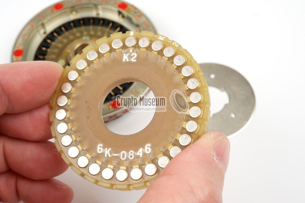
Each face of the core carries thirty flat pads. The spring contacts belong to the wheel body. A core turned over presents its wiring mirrored and running the other way. In the simulator, if a core wires contact x to W(x) with side 1 out, then with side 2 out the wiring traversed in the same direction is the inverse of x → −W(−x) (counting from zero, modulo 30). This rule is derived from the published wiring rather than copied. It reproduces CrypTool 2’s separately tabulated flipped cores for all three of its series, and the published test vectors with flipped cores. A wheel can therefore present any of its ten candidate cores, either way round, at any of thirty core settings: 600 different wirings, each combinable with thirty ring settings.
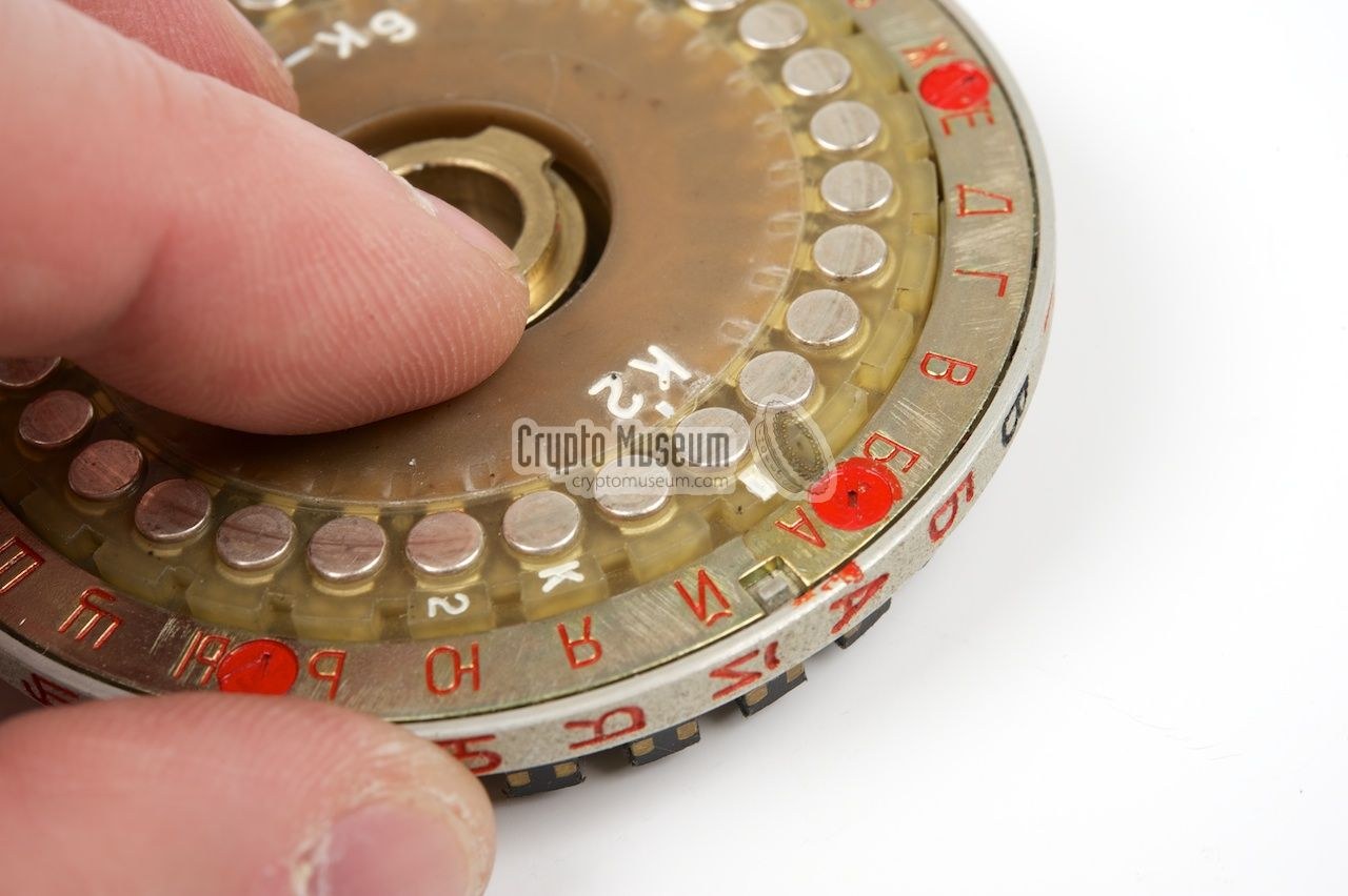
The 1978 East German manual’s daily key table for adjustable wheels has five lines, one for each choice: wheel order, ring settings, core order, core sides and core settings. The operator laid out the bodies, set their rings, laid the cores beside them in the order of the third line, inserted each with the side given by the fourth line and the mark set by the fifth, secured them with their lock-washers and slid the wheels onto the spindle (NVA A 040/1/321, section 7.2.3). Reuvers and Simons note that Crypto Museum has found no evidence that adjustable wheels were used in the older M-125, although they fit it. They are mostly found with the M-125-3 (Reference Manual 3.3.3). A special opening tool for the wheels exists. Volume 10 sets a full daily key on the simulator.
3.11 What the Drum Bought
Set against the machine it is so often compared with, the drum closes off, one by one, the weaknesses that let the Enigma be broken:
Table 5 — Set against the machine it is so often compared with, the drum closes off, one by one, the weaknesses that let the Enigma be broken
| Enigma (Army, 1939) | Fialka drum | |
|---|---|---|
| Wheels in use | 3 (of 5) | 10 (all of a set of 10) |
| Contacts | 26 | 30 |
| Stepping | one fast wheel; regular odometer carry | two fast wheels; all ten can move on any key |
| Direction | all one way | adjacent wheels opposite |
| Turnover points | 1 notch per wheel | 7 to 23 pins per wheel, blocking rather than driving |
| Slowest wheel | once in 650 letters | about once in 40 (demonstration key) |
| Stepping cycle | 16,900 letters | 24,300,000 per chain (demonstration key) |
| Wiring changes | wheel order and ring setting | also core order, core side and core setting (from 1978) |
| Letter to itself | impossible | possible (Volume 4) |
The table does not show whether the Fialka was secure. Volume 7 sets out what is and is not known about Western attacks on it, and Volume 10 measures the key space. What it shows is that the designers knew exactly how the Enigma had been attacked. A fast wheel moving alone, a middle wheel turning over at a fixed point and a slow wheel that hardly moved had given the Polish and British codebreakers fixed points to work from. In the Fialka, none of those regularities survives.
Sources
- Paul Reuvers & Marc Simons, Fialka M-125 Reference Manual, version 2.0, Crypto Museum (sections 3.3, “Wheels”, and 3.7, “Sequence of Events”): PDF (Library copy); about the manual.
- Crypto Museum, “Fialka wiring” (series 68, 3K, 5K, 6K, 4K and 7K; definitions; XML files for simulator authors, v0.10, 25 December 2017): cryptomuseum.com/crypto/fialka/wiring.htm.
- Crypto Museum, “Fialka cipher wheels”: cryptomuseum.com/crypto/fialka/wheels.htm.
- Nationale Volksarmee, A 040/1/321 — System M-125 (M-125-3MN and M-125-MN) — Operations manual, 1978, English translation by “JMcC”: PDF (Library copy).
- E. Antal & P. Zajac, “Key Space and Period of Fialka M-125 Cipher Machine”, Cryptologia 39(2), 2015, 126–144: doi:10.1080/01611194.2014.915264.
- Worked examples:
03-outputs/tools/fialka_sim.py(this series), validated as described in Volume 9.
Next — Volume 4: How It Works II — The Card Reader, the Reflector, Keyboard, Printer and Tape. The punched key card that took the plugboard’s place, with thirty holes in a thirty-by-thirty grid; the reflector that lets a letter encipher to itself and the three transistors that make coding and decoding different; the keyboard with its mechanical five-bit encoder; the print head that marks a failed letter with an asterisk; the tape punch and reader; the M-125-3’s numbers-only mode; and the power supply built to defeat eavesdroppers on the mains.
Comments (0)