Digi-Comp · Volume 4
Digi-Comp — Volume 4 — Programming Digi-Comp I — The Manual's Problems Worked
The 1963 manual's fifteen experiments as coding sheets and state tables: counting up and down, an elevator, two bank locks, a riddle about truth-tellers, a space-ship check-out, a number-guessing trick, Nim, and the serial comparator, adder, subtractor and multiplier — every result run on the series' simulator
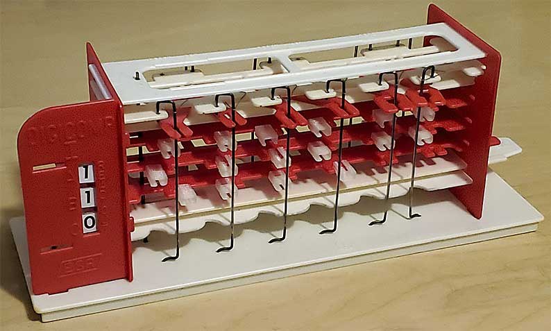
4.1 About This Volume
Volume 3 explained the mechanism: three flip-flops, six logic rods that each test an AND of conditions, and clock tubes that say which flip-flops each rod sets or resets. This volume uses that mechanism. It works through every program in E.S.R.’s 1963 instruction manual, from the check-out problem on page 4 to binary multiplication on page 27, and shows for each one the coding sheet, what the program means in words, and what the machine does with it.
Every coding sheet here was transcribed from a 300-dpi scan of the manual kept by the Friends of DigiComp at the Internet Archive (archive.org/details/digicomp_i), and every result was produced by the series’ simulator, digicomp_sim.py, not worked out by hand. Run as python3 digicomp_sim.py --dc1 counter (or any of the other program names listed by --dc1-list) it prints the coding sheet, the rods in words and the complete state table. Its self-test checks every result the manual prints and every behaviour the manual describes; all 30 Digi-Comp I checks pass. In one case the simulator found something the manual does not mention, and that is reported where it occurs.
Throughout, a state is written as three digits A B C, which is the read-out column read from top to bottom. A program that counts treats A as the ones bit, so 100 is one and 001 is four. The manual’s experiments use Front Panel Cards, printed slips that slide into the front panel and label the three read-outs for each experiment (“2ND FLOOR / 1ST FLOOR / UP-DOWN” for the elevator, for instance).
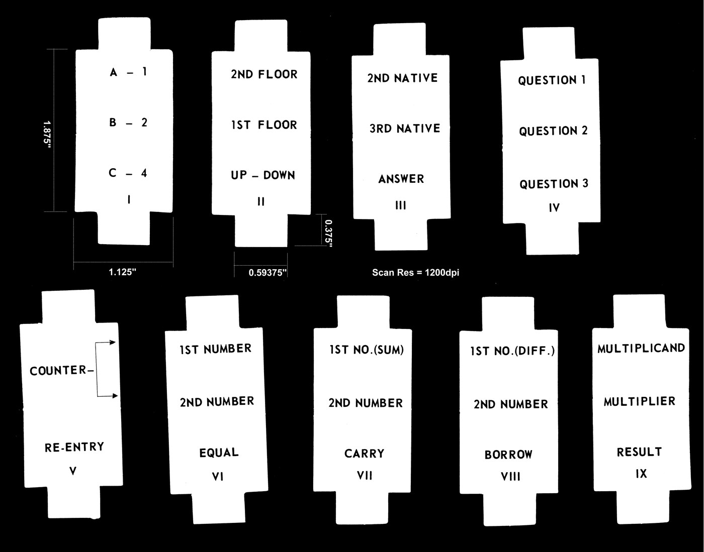
4.2 Three Kinds of Program
The fifteen experiments fall into three kinds, and it helps to know which kind a program is before loading it.
- Sequences. The operator sets a starting state and cycles the clock repeatedly. The program is a next-state function, and the interesting thing is the path the state follows. The check-out problem, the count-down and the binary counter are of this kind.
- One-cycle functions. The operator enters some bits by hand, cycles the clock once and reads the answer. The program is a function from the entered bits to the result. The elevator, the bank lock, the Ho-Hum riddle, the space-ship check-out and Guess the Number work this way. So does Nim, in which each cycle is the computer’s move.
- Serial operations. The operator enters one pair of bits, cycles once, copies the result, enters the next pair and cycles again, leaving one flip-flop alone so that it carries something — a carry, a borrow or a comparison — from one cycle to the next. The comparator, adder and subtractor work this way, and the multiplier works one bit-pair at a time with no carry.
4.3 Sequences: Counting by Clock
4.3.1 Experiment 1: the check-out problem
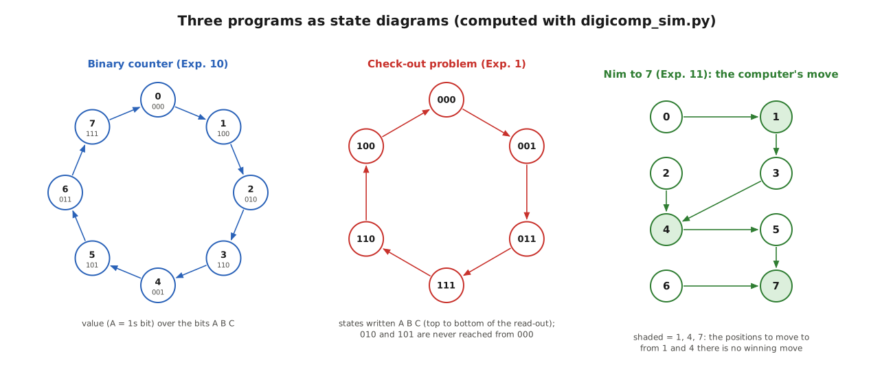
The first program is the one Volume 3 followed through cycle by cycle. Each flip-flop takes the old value of the one below it, and C takes the complement of the old A. From 000 it runs 000 → 001 → 011 → 111 → 110 → 100 → 000, six states round a ring, which matches the manual’s list of read-outs “after the first … sixth clock cycle” (p. 4). The two states that are not in the ring, 010 and 101, swap with each other on every cycle; the manual sensibly says to start from 000.
4.3.2 Experiment 2: Final Count Down
The count-down “will automatically signal the BLAST OFF of a space ship from Cape Canaveral at the right time” (p. 8). The coding sheet is:
Table 1 — The count-down "will automatically signal the BLAST OFF of a space ship from Cape Canaveral at the right time" (p. 8). The coding sheet is
| T | F | 1 | T | F | 2 | T | F | 3 | T | F | 4 | T | F | 5 | T | F | 6 | |
|---|---|---|---|---|---|---|---|---|---|---|---|---|---|---|---|---|---|---|
| A | L | C | L | C | L | L | L | L | ||||||||||
| B | L | C | L | C | L | L | ||||||||||||
| C | L | C | L | C |
In words: rod 1 resets A when A = 1; rod 2 sets A when A = 0, so A toggles on every cycle. Rod 3 resets B when A = 0 and B = 1, and rod 4 sets B when A = 0 and B = 0, so B toggles whenever A was 0. Rods 5 and 6 toggle C whenever A and B were both 0. A toggles always, B when the bit below borrows, C when both lower bits borrow: that is a binary down-counter. Started at 111 (seven), the simulator gives 7, 6, 5, 4, 3, 2, 1, 0 — “DIGI-COMP has counted 7 clock cycles starting at 1 1 1 and ending at 0 0 0” (p. 8). Cycled once more, it wraps round to 7.
4.3.3 Experiment 10: the binary counter
The up-counter (p. 21) is the count-down with every condition on a lower bit inverted: B toggles when A was 1, and C toggles when A and B were both 1.
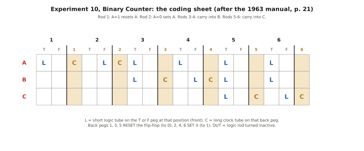
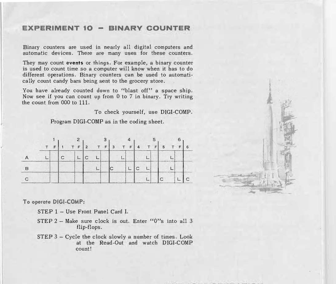
The simulator’s complete state table for the counter, written as values (A = ones bit), is:
Table 2 — The simulator's complete state table for the counter, written as values (A = ones bit), is
| Now | 0 | 1 | 2 | 3 | 4 | 5 | 6 | 7 |
|---|---|---|---|---|---|---|---|---|
| Next | 1 | 2 | 3 | 4 | 5 | 6 | 7 | 0 |
The counter uses every one of the six rods and twelve of the 22 logic tubes. Rods 5 and 6 each need three conditions. The counter is about as large a sequence as the machine can hold, which is why the manual’s suggested exercise on page 28 — an “automatic counter” that counts four cycles and then stops — is harder than it looks. Stopping means making one state its own successor, and there are no rods to spare for it unless the count uses fewer bits.
4.4 One-Cycle Functions: Logic, Locks and Riddles
4.4.1 Programming: the AND operation
Chapter II of the manual introduces programming with a rainy-day syllogism — rubbers AND raincoat, then not wet — and four “statements” relating flip-flops A, B and C (p. 12-14). The first, A AND B = C, is one rod: tubes on the T pegs of A and B at position 2 and a clock tube on C at peg 2. The second, “if A is false and B is true then C is false”, is rod 1 with tubes on A-F and B-T and a clock tube on C at peg 1, a reset. The answer page (p. 28) gives statements 3 and 4 as rods 3 and 5, each resetting C. The simulator confirms each: with A = B = 1 rod 2 sets C; with A = 1, B = 0 it stays 0; with A = 0, B = 1 rod 1 resets it.
The important idea is in the second statement. The machine cannot “make C equal to something”; it can only set or reset. A program that means “C becomes A AND B” therefore needs two kinds of rod: some that set C in the cases where the answer is 1, and others that reset it where the answer is 0. A rod that is not needed in a case simply leaves C alone. That idea runs through every program that follows.
4.4.2 Experiment 3: the automatic elevator
The elevator uses Card II: A lights “2ND FLOOR”, B lights “1ST FLOOR”, and C, at the bottom, is the “UP-DOWN” button. The manual’s sheet (p. 15) has no tubes on A or B at all:
Table 3 — The elevator uses Card II: A lights "2ND FLOOR", B lights "1ST FLOOR", and C, at the bottom, is the "UP-DOWN" button. The manual's sheet (p. 15) has no tubes on A or B at all
| Rod | Moves in when | Does |
|---|---|---|
| 1 | C = 0 | RESET A |
| 2 | C = 1 | SET A |
| 3 | C = 1 | RESET B |
| 4 | C = 0 | SET B |
So one cycle copies the button into the floor lamps: up (C = 1) gives A = 1, B = 0, the second floor; down gives the first. The simulator’s table is the same whatever the lamps showed before. Rods 5 and 6 are left active with no tubes at all, so they drop in on every cycle, but there are no clock tubes at positions 5 and 6, so they move nothing. The manual says the elevator “uses MEMORY” because it “is required to REMEMBER at which of the two floors it has stopped”: the lamps stay as they are until the button changes and the clock is cycled again.
4.4.3 Experiment 4: the bank lock
“Each morning the president of the MONEY bank has to open the bank vault. It is a combination lock using binary numbers” (p. 16). The owner guesses a three-bit combination, enters it by hand and cycles once; the vault is open if the read-out then shows 111. Rods 3 and 5 are out, and the four active rods are:
Table 4 — "Each morning the president of the MONEY bank has to open the bank vault. It is a combination lock using binary numbers" (p. 16). The owner guesses a three-bit combination, enters it by hand and cycles once; the vault is open if the read-out then shows 111. Rods 3 and 5 are out, and the four active rods are
| Rod | Moves in when | Does |
|---|---|---|
| 1 | A = 1, B = 1, C = 1 | RESET A |
| 2 | A = 1, B = 0, C = 1 | SET A |
| 4 | A = 1, B = 0, C = 1 | SET B |
| 6 | A = 1, B = 0, C = 1 | SET C |
Run over all eight possible guesses, the simulator finds exactly one that opens the lock, 101, which rods 2, 4 and 6 turn into 111. Every other guess is left as it was — with one exception. The obvious cheat, entering 111 directly, is caught by rod 1, which knocks A back to 0 and leaves 011. The chance of opening the vault at the first try, the manual’s question, is one in eight.
4.4.4 Experiment 5: the sequential bank lock
The second lock “requires two binary numbers in a particular order” (p. 16). The owner starts at 000 and enters two-bit guesses in A and B only. Rods 1, 3 and 5 are out. Rod 6 sets C when A = 1, B = 0 and C = 0: the first number is 10 (A = 1, B = 0), and the sign that it was right is that C turns to 1. Rods 2 and 4 then set A and B when A = 0, B = 1 and C = 1: the second number is 01, and it leaves 111. The manual’s step 6 tells the guesser to choose the second number from “0 0, 0 1 or 1 0, not 1 1”, and the simulator shows why the rule is needed: entering 11 with C already set would show 111 without any rod moving at all. With the rule, the chance of opening the vault first time is one in four for each number, one in sixteen in all.
4.4.5 Experiment 6: the Ho-Hum riddle
“In the Pacific Ocean there are two neighboring islands … the natives of island HO always tell the truth while the natives of island HUM always tell falsehoods” (p. 17). The first native answers in his own language; the second says “He say he belong HUM”; the third says “No, first man say he belong HO”. To which island does the third native belong?
The logic is a classic. Any native, asked where he comes from, says HO — the truthful one because it is true, the liar because it is false. So the second native, who reports “HUM”, is lying, and the third, who reports “HO”, is telling the truth. The third native is from HO. In general, a native who reports that the first man said HO is telling the truth, and so the third native’s island can be read straight off his own report.
The machine is programmed (Card III) with the second native’s report in A and the third native’s in B, 1 for HO and 0 for HUM, and C gives the answer. The coding sheet as printed has rods 2 and 3 out and:
Table 5 — The machine is programmed (Card III) with the second native's report in A and the third native's in B, 1 for HO and 0 for HUM, and C gives the answer. The coding sheet as printed has rods 2 and 3 out and
| Rod | Moves in when | Does |
|---|---|---|
| 1 | A = 1 | RESET C |
| 4 | A = 0, B = 1 | SET C |
| 5 | A = 0, B = 0 | RESET C |
| 6 | A = 1, B = 1 | SET C |
With the riddle’s own answers, A = 0 (HUM) and B = 1 (HO), only rod 4 drops in, C is set, and the read-out says the third native is from HO: correct. With A = 0 the program gives C = B in both cases, as the logic requires.
The manual adds: “Try entering other answers for the 2nd and 3rd Natives. DIGI-COMP will always correctly tell you from where the third native comes.” The simulator, run over all four inputs, disagrees in one case. With A = 1 and B = 1 — both natives reporting HO — rod 1 (A = 1) and rod 6 (A = 1, B = 1) both drop in, and the program asks for C to be reset and set in the same cycle. That is the mechanical conflict described in Volume 3. With A = 1, B = 0 only rod 1 acts and C is reset, which is right. The scan was checked at 300 dpi: there is no tube on B at position 1. If rod 1 had a second tube, on the F peg of B, it would act only when A = 1 and B = 0, the conflict would disappear, and the program would give C = B for every input, as the text promises. Whether the missing tube is a printing slip or was never there cannot be told from the manual alone; on a real machine the cycle with A = B = 1 should be expected to jam.
4.4.6 Experiment 7: the space-ship check-out
“This is the last moment before ‘blast off’” (p. 18). Three systems, oxygen, controls and radio, must each be checked against a stored value. The owner enters a three-bit guess, cycles once, and looks for 111, “A-O.K.” The trick is that the logic rods are switched in one at a time. With only rods 2 and 3 active, the simulator finds that just one entry gives 111: 011, which rod 2 completes by setting A. Rod 3 is there to reject the cheat: 111 entered directly is turned into 101. Turning rod 4 on adds a second accepted value, 101 (rod 4 sets B), and turning rod 6 on adds the third, 110 (rod 6 sets C). The stored values for oxygen, controls and radio are therefore 0-1-1, 1-0-1 and 1-1-0 as read down the column. Each is “one bit short” of 111, and the rod that checks it supplies the missing bit.
4.4.7 Experiment 8: Guess the Number
A friend thinks of a number from 0 to 7 and answers three questions: is it even; is it 0, 1, 2 or 3; and “add 10 to the number and divide the result by 6; is the remainder 0, 1, 2 or 3?” (p. 19). The answers go into A, B and C (1 for yes, using Card IV) and one cycle turns them into the number.
The program has a pleasing logic. Rods 1 and 2 invert A: the number is even exactly when its ones bit is 0. Rods 5 and 6 invert C as well (rod 5 resets C when B and C are both 1, rod 6 sets it when both are 0, and otherwise C already holds the inverse of B): the number is 0 to 3 exactly when its fours bit is 0. The third question is the clever one. Its answer is yes for 2, 3, 4 and 5 and no for 0, 1, 6 and 7, and the twos bit turns out to be 1 exactly when the second and third answers agree. Rods 3 and 4 compute that. The simulator confirms all eight cases:
Table 6 — The program has a pleasing logic. Rods 1 and 2 invert A: the number is even exactly when its ones bit is 0. Rods 5 and 6 invert C as well (rod 5 resets C when B and C are both 1, rod 6 sets it when both are 0, and otherwise C already holds the inverse of B): the number is 0 to 3 exactly when its fours bit is 0. The third question is the clever one. Its answer is yes for 2, 3, 4 and 5 and no for 0, 1, 6 and 7, and the twos bit turns out to be 1 exactly when the second and third answers agree. Rods 3 and 4 compute that. The simulator confirms all eight cases
| Number | 0 | 1 | 2 | 3 | 4 | 5 | 6 | 7 |
|---|---|---|---|---|---|---|---|---|
| Answers (even, 0-3, remainder 0-3) | 1 1 0 | 0 1 0 | 1 1 1 | 0 1 1 | 1 0 1 | 0 0 1 | 1 0 0 | 0 0 0 |
| Read-out after one cycle (value) | 0 | 1 | 2 | 3 | 4 | 5 | 6 | 7 |
4.4.8 Experiment 9: Space Capsule Re-Entry
Here the machine becomes a sequential lock again, but the lock counts. “Augie, the Astronaut, can re-enter the earth’s atmosphere by pushing his Re-entry buttons in the correct sequence” (p. 20). C is the button; A and B are a two-bit counter (Card V). Each cycle with the correct button advances the counter; a wrong one sends it back to 00; and once it reaches 11 “DIGI-COMP has automatically STOPPED”. The simulator finds the secret: the button must be 1, 0, 1. The counter then runs 00 → 10 → 01 → 11 (written A B), every wrong press returns it to 00, and from 11 neither button changes anything. Four rods do it, with rods 5 and 6 out.
4.5 Nim: the Machine Plays a Game
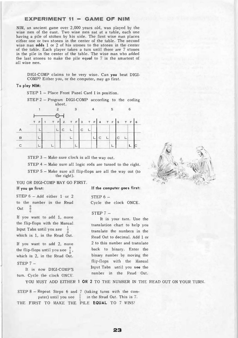
The manual’s Nim is a simple take-away game in reverse. Two players take turns adding one or two stones to a pile, and “the wise man who added the last stones to make the pile equal to 7 is the smartest of all wise men” (p. 23). The pile is held in binary, A as the ones bit. On the human’s turn the player moves the flip-flops by hand to the new total; on the computer’s turn the player cycles the clock once.
The winning strategy is to leave the pile at 1, 4 or 7: from any of those, the opponent can add only one or two, and the player can always restore the pile to the next of them. The program is the first in the manual to use a double slider, joining rods 1 and 2 to clock rod 2, so that two different conditions both set A. The simulator gives the computer’s move from every pile:
Table 7 — The winning strategy is to leave the pile at 1, 4 or 7: from any of those, the opponent can add only one or two, and the player can always restore the pile to the next of them. The program is the first in the manual to use a double slider, joining rods 1 and 2 to clock rod 2, so that two different conditions both set A. The simulator gives the computer's move from every pile
| Pile before | 0 | 1 | 2 | 3 | 4 | 5 | 6 |
|---|---|---|---|---|---|---|---|
| Computer leaves | 1 | 3 | 4 | 4 | 5 | 7 | 7 |
| It added | 1 | 2 | 2 | 1 | 1 | 2 | 1 |
Every move is legal, and from 0, 2, 3, 5 and 6 the computer reaches 1, 4 or 7. From 1 and 4 there is no winning move, and it simply adds one or two. If the computer goes first it moves to 1 and cannot lose. A complete game from the simulator: computer 0 → 1; human adds 2 → 3; computer → 4; human adds 1 → 5; computer → 7 and wins.
Nim was a theme E.S.R. returned to. Volume 7 describes Dr. Nim, John Godfrey’s marble-driven Nim player of 1966, which plays a different version: fifteen marbles, and whoever takes the last one loses.
4.6 Serial Arithmetic: One Bit at a Time
The last four experiments turn three flip-flops into arithmetic units that handle numbers of any length, by working one bit position per clock cycle. The operator plays the part of the shift register. Two of the flip-flops receive the two input bits; the third keeps whatever must pass from one bit position to the next, and must not be touched between cycles.
4.6.1 The OR operation and the double slider
Before the arithmetic, the manual introduces the double slider with the smallest possible example (p. 22): rod 1 with a tube on A-T, rod 2 with a tube on B-T, both joined by a double slider to clock rod 2, and a clock tube on C at peg 2. Rods 3 to 6 are out. “If you move A to ‘1’ OR B to ‘1’ then C will be set when the clock is cycled.” The simulator agrees: C is set for inputs 10, 01 and 11, and left alone for 00.
4.6.2 Experiment 12: comparing two numbers
The comparator (p. 24) uses Card VI and starts with C = 1. The operator enters the lowest bits of the two numbers in A and B, cycles, then the next pair, and so on. While the bits agree, C stays 1; at the first pair that differs, C drops to 0 and stays there for good. Two double sliders do the work: rods 3 (A = 1, B = 0) and 4 (A = 0, B = 1) are joined to clock rod 3, which resets C; rods 1 and 2 are joined to clock rod 2 but only ever set C when it is already set. On the manual’s example, A = 10110 and B = 11110 entered from the right, the simulator shows C = 1 after the first three pairs (00, 11, 11) and C = 0 after the fourth (01): the numbers differ.
4.6.3 Experiment 13: the serial adder
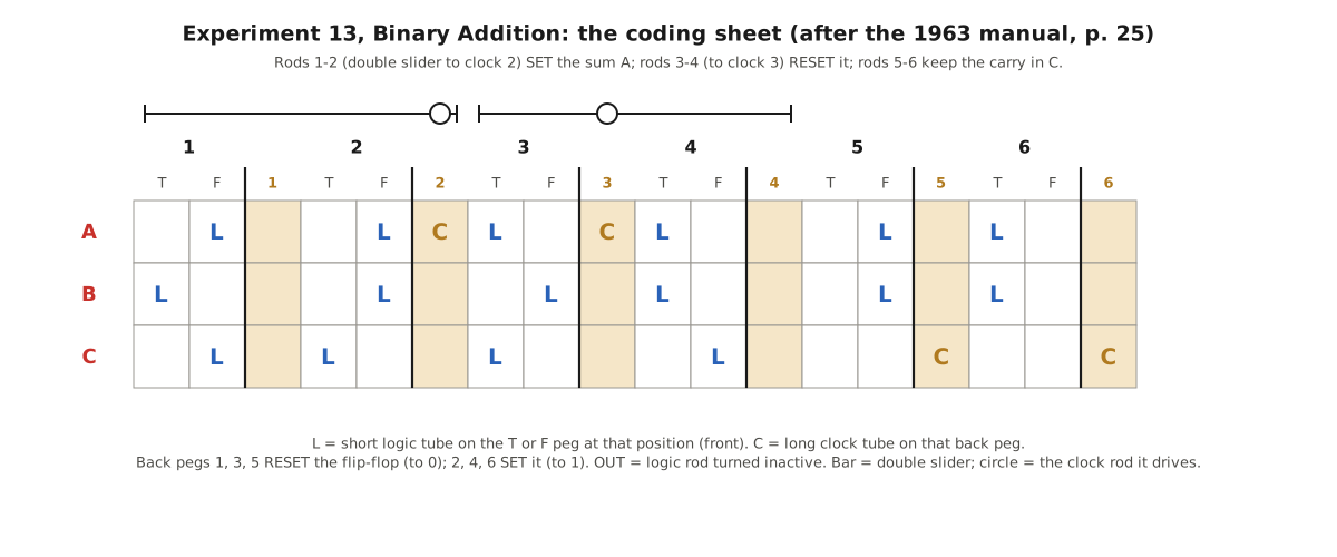
The adder (p. 25, Card VII) is the most elaborate program in the manual. The operator puts one bit of each number in A and B, C holding the carry (0 at the start), and cycles once; “A will remember the sum and C will remember the carry”. The sum is A XOR B XOR C and the new carry is the majority of the three. The coding sheet in words:
Table 8 — The adder (p. 25, Card VII) is the most elaborate program in the manual. The operator puts one bit of each number in A and B, C holding the carry (0 at the start), and cycles once; "A will remember the sum and C will remember the carry". The sum is A XOR B XOR C and the new carry is the majority of the three. The coding sheet in words
| Rods | Condition | Action | Meaning |
|---|---|---|---|
| 1 or 2 | A=0, B=1, C=0 or A=0, B=0, C=1 | SET A | sum is 1 although A was 0 |
| 3 or 4 | A=1, B=0, C=1 or A=1, B=1, C=0 | RESET A | sum is 0 although A was 1 |
| 5 | A=0, B=0 | RESET C | no carry out |
| 6 | A=1, B=1 | SET C | carry out |
In the other four cases A already holds the correct sum, and in the cases where exactly one of A and B is 1 the carry passes through unchanged in C. The double sliders matter: without them, the four sum terms would need four separate clock rods, and there would be none left for the carry.
The manual’s example adds 101 to 111. The simulator, one cycle per bit, lowest first:
Table 9 — The manual's example adds 101 to 111. The simulator, one cycle per bit, lowest first
| Cycle | A (bit of first number) | B (bit of second) | C before (carry in) | A after (sum bit) | C after (carry out) |
|---|---|---|---|---|---|
| 1 | 1 | 1 | 0 | 0 | 1 |
| 2 | 0 | 1 | 1 | 0 | 1 |
| 3 | 1 | 1 | 1 | 1 | 1 |
Reading the sum bits from the last to the first, after the final carry: 1100, which is twelve, the manual’s answer (“SUM (Answer in A) 1 1 0 0”). The simulator’s self-test also runs the adder on every pair of four-bit numbers, 256 cases, and gets every sum right.
4.6.4 Experiment 14: the serial subtractor
“Compare this coding sheet with the one for the binary adder. Notice the only difference is at Position 5 and 6” (p. 26). The difference bit is computed exactly as the sum bit was; only the borrow rule changes. Rod 5 now clears the borrow when A = 1 and B = 0, and rod 6 sets it when A = 0 and B = 1. The manual’s example takes 0111 (seven) from 1010 (ten):
Table 10 — "Compare this coding sheet with the one for the binary adder. Notice the only difference is at Position 5 and 6" (p. 26). The difference bit is computed exactly as the sum bit was; only the borrow rule changes. Rod 5 now clears the borrow when A = 1 and B = 0, and rod 6 sets it when A = 0 and B = 1. The manual's example takes 0111 (seven) from 1010 (ten)
| Cycle | A (first) | B (second) | Borrow in | Difference bit | Borrow out |
|---|---|---|---|---|---|
| 1 | 0 | 1 | 0 | 1 | 1 |
| 2 | 1 | 1 | 1 | 1 | 1 |
| 3 | 0 | 1 | 1 | 0 | 1 |
| 4 | 1 | 0 | 1 | 0 | 0 |
The difference is 0011, three, with the borrows 1, 1, 1 exactly as printed. The self-test runs all 136 four-bit cases with the second number no larger than the first, as the manual requires (“the number subtracted must be less than, or equal to the number from which it is being subtracted”).
4.6.5 Experiment 15: multiplication
Binary multiplication needs only the table 0 × 0 = 0 × 1 = 1 × 0 = 0 and 1 × 1 = 1, so the multiplier program (p. 27, Card IX) is just an AND: rods 3 and 4, joined by a double slider to clock rod 3, reset C if A = 0 or B = 0, and rod 6 sets C if both are 1. The owner enters one bit of the multiplicand in A and one bit of the multiplier in B, cycles, and copies C. Going through every bit of the multiplicand for each bit of the multiplier gives the partial products, which are written down shifted, as in long multiplication. “You may use DIGI-COMP to add the partial products to get the final result (use the Binary Adder Experiment).”
The manual’s example is 1101 × 1101, thirteen times thirteen. The simulator produces the four partial products 1101, 0000, 1101 and 1101, and then — using the adder program, a bit at a time — adds them up to 10101001, which is 169, the answer the manual prints. That last step is honest about Digi-Comp I: it multiplies one bit by one bit, and the person at the table does the rest. It is still a fair picture of what a serial computer of the 1950s did, with the operator playing the part of the shift registers and the control unit.
4.7 What the Programs Teach
Taken together, the fifteen experiments are a short course in digital design, and they make the same few points over and over.
- Set and reset, not “equals”. Every program has to say separately when a flip-flop becomes 1 and when it becomes 0, and leaves it alone otherwise. A designer who forgets the second half gets a flip-flop that never changes back; one who overlaps them gets a jam.
- Terms are scarce. Six rods are not many. The counter uses them all; the adder needs both double sliders. A good deal of the manual’s ingenuity goes into making functions fit — Guess the Number’s choice of a third question that makes the middle bit a simple comparison is a fine example.
- Programs can be checked exhaustively. With only eight states, every program can be tested on every input, and doing so is how the Ho-Hum conflict above was found. The simulator does in a fraction of a second what an owner in 1963 could have done in ten minutes with a pencil, and its state tables are the most compact way to describe what each sheet does.
- Sequence comes from feedback; arithmetic from repetition. A counter is a function fed back into itself; an adder is a function applied once per bit with one flip-flop carrying the memory. Every later computer in this series is built from those two ideas.
The manual ends with two problems “for you to program”: an automatic counter that counts four cycles and then stops, and a riddle about which of three boys caught a fish. Both can be solved within the six rods, and both are good exercises for the simulator before the tubes go on.
Next — Volume 5: Digi-Comp II — Marbles, Toggles and the Story of the Rolling-Ball Computer. E.S.R.’s second machine throws away the clock lever and the rods: a tilted board, marbles for pulses, plastic toggles for flip-flops, and a computer that adds, multiplies and stops itself under gravity alone.
Comments (0)