SIGABA · Volume 4
SIGABA — Volume 4 — How It Works II — The Control and Index Banks
Four live wires, a meter of three wheels, nine bundles of contacts, five wheels that never turn, and one letter traced through all fifteen to show which cipher wheels step and why
4.1 About This Volume
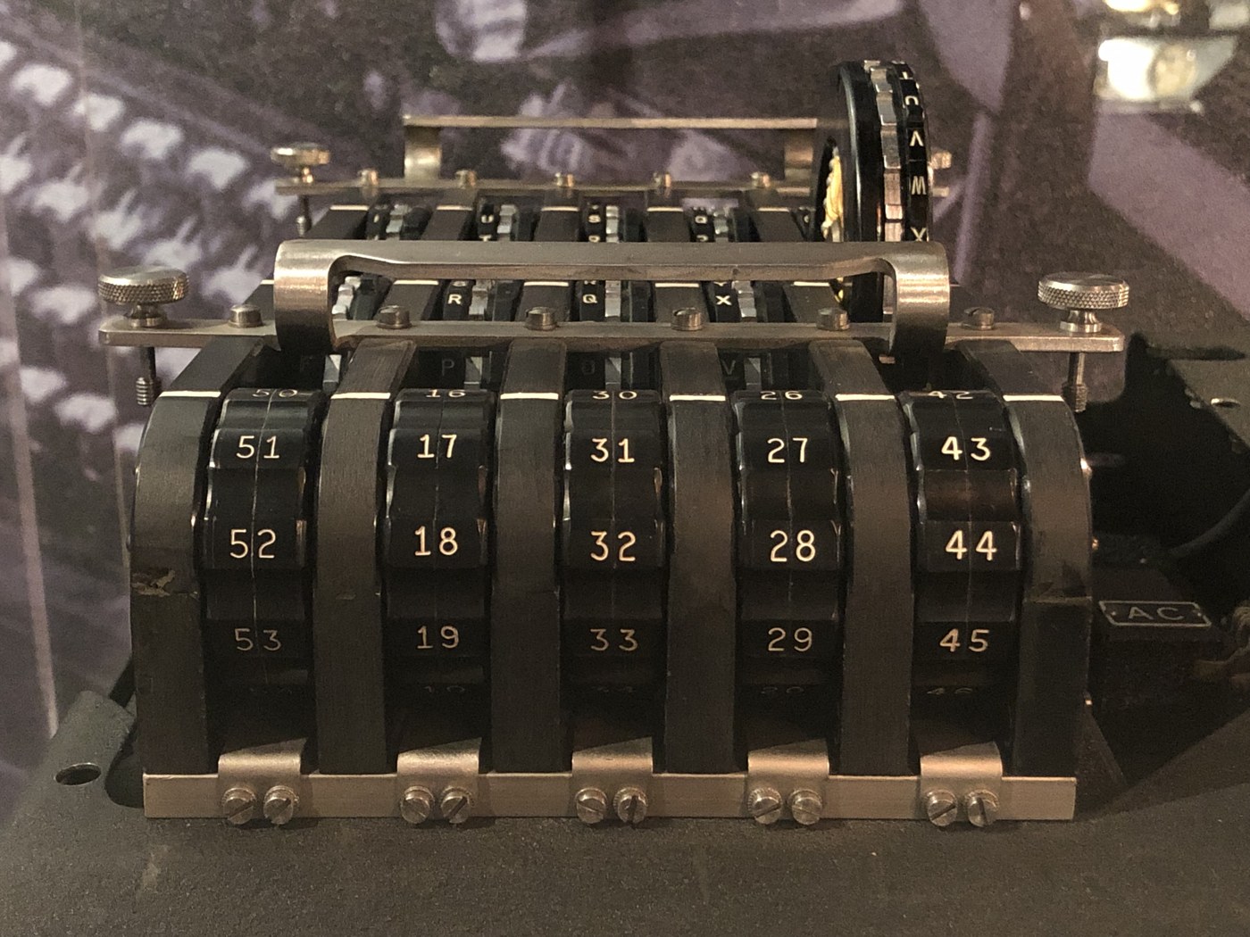
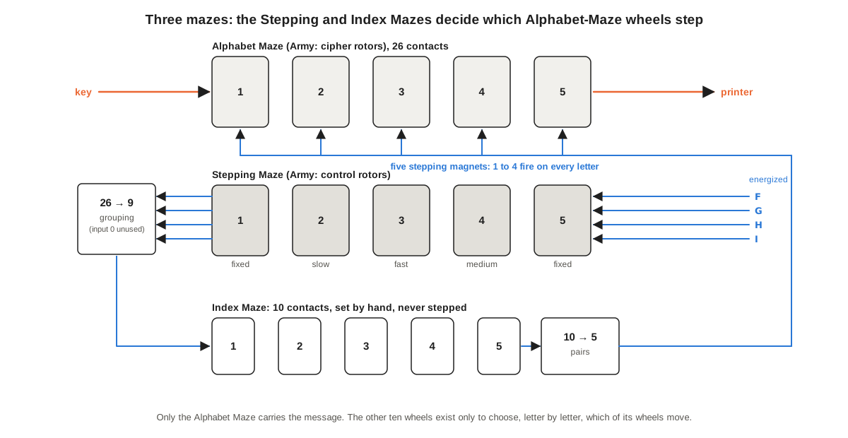
Volume 3 followed a letter through the five wheels of the Alphabet Maze and ended on the point that makes the SIGABA what it is: the cipher depends on how those wheels move. This volume is about the ten wheels that decide it. The Stepping Maze (Army: control rotors) is a second bank of five code wheels, through which four currents flow on every keystroke. The Index Maze (Army: index rotors) is a bank of five small ten-contact wheels that take those currents and deliver them to the stepping magnets of the Alphabet Maze. Between the two banks, and after the second, is fixed wiring that is the same in every machine. The design idea is Frank Rowlett’s and William Friedman’s of 1935, refined by the Navy’s Laurance Safford and the engineers of Teletype Corporation (Volume 2 tells that story).
The volume describes each part as the 1944 Navy manual, CSP 1100(C), describes it, and as Richard Pekelney’s emulation of the USS Pampanito machine implements it; it checks the stepping rule against a table printed in the manual itself; it shows how the fixed wiring weights the odds of each cipher wheel stepping; and it traces one letter through all fifteen wheels with the unit’s simulator, 03-outputs/tools/sigaba_sim.py.
4.2 Four Live Wires
On every cycle, at the moment the stepping contact closes (Volume 3), current is applied to four of the 26 contacts at the right-hand end of the Stepping Maze, the contacts in the positions of the letters F, G, H and I. The other 22 are dead. The four currents pass leftwards through the five wheels and come out at the left-hand end on four of the 26 contacts there. Because each wheel is a one-to-one wiring, the four never merge inside the maze: they always leave on four different contacts. Which four depends on the wirings, orientations and positions of all five Stepping-Maze wheels, and so changes from letter to letter as the wheels move.
Why four? The 1944 patent application, written by Safford and Donald Seiler, gives the reasoning. The number of live inputs has to be “less than the number of wheels being stepped through the index maze, in this case five. If five input connections are employed, all of the coding wheels 61 may be stepped at one time and thus the scrambling of the circuits would be diminished and if fewer than four are employed there is a possibility that none of the coding wheels 61 might be stepped at some one time” (US Patent 6,175,625, col. 6; Library copy). All five wheels stepping together would leave their relative positions unchanged, which is wasted motion; no wheel stepping would repeat the last substitution. Four live wires guarantee that at least one wheel steps and at most four do.
4.3 The Meter
Three of the five Stepping-Maze wheels move; the two at the ends never do. The rule is in CSP 1100(C) par. 203(d)(2):
The center Code Wheel steps once for each letter during the process of encipherment or decipherment. When the center Code Wheel is aligned to “O”, the cam-lobe closes a contact and #4 Code Wheel (immediately to the right of the center Code Wheel) will step once on the next letter of the encipherment or decipherment. When both the center and #4 Code Wheels of the Stepping Maze are aligned to “O”, #2 Code Wheel (immediately to the left of the center Code Wheel) will step …
So wheel 3 is the fast wheel, wheel 4 the medium and wheel 2 the slow, and they turn like the wheels of a gas meter, with the oddity that the fast wheel sits between the other two. The patent gives the mechanism: a boss on the rim of each wheel, once per revolution, “moves contact strip 123 to close a circuit through contacts 124 and 125 and connects wire 119 to the stepping magnet 93 of the fourth control wheel”, “thus effecting meterwise operation of the third, fourth, and second control wheels” (US 6,175,625, col. 6; Library copy). The same cam-lobes stop the wheels at O when zeroizing (Volume 3), and the zeroizing contacts of wheels 3 and 4 carry an extra spring for the meter (CSP 1100(C) par. 511).
The three moving wheels between them take 26 × 26 × 26 = 17,576 letters to return to their starting positions, which Timothy Mucklow’s NSA history calls the cycle length of the control maze (Mucklow 2015, Appendix B). The rule that no message part exceed 350 five-letter groups, 1,750 letters (Volume 5), kept every message far inside one turn of that meter.
Two details of the rule are easy to get wrong, and both decide whether a simulator agrees with a real machine. First, the test is made on the position at the start of the cycle: if wheel 3 reads O when a key is pressed, wheel 4 steps on that cycle, as wheel 3 moves off O. Second, the direction: a normal wheel’s reading goes down the alphabet, O, N, M, and a reversed wheel’s goes up. Pekelney’s emulation got the slow wheel wrong at first and corrected it in February 1998, so that “slow control rotor now only moves when the medium rotor moves” (ECMApp source, revision 1.01), and George Lasry found the same error, among others, in the simulator used for the MysteryTwister C3 challenges (Lasry 2019, note 14; Library copy).
The manual itself settles both points. Its paragraph 519, “Stepping Checks”, gives repair crews a table of the readings both mazes must show at chosen step numbers from 0 to 10,000 after zeroizing, with wheel set CSP 1336 in the order 31-32-33-34-35 / 36-37-38-39-40, all normal, and index setting 18-26-33-43-51. The Stepping-Maze column depends only on the stepping rule, not on any wiring. The simulator reproduces all 56 readings in it, from ONNNO at step 1 to OZYTO at step 10,000.
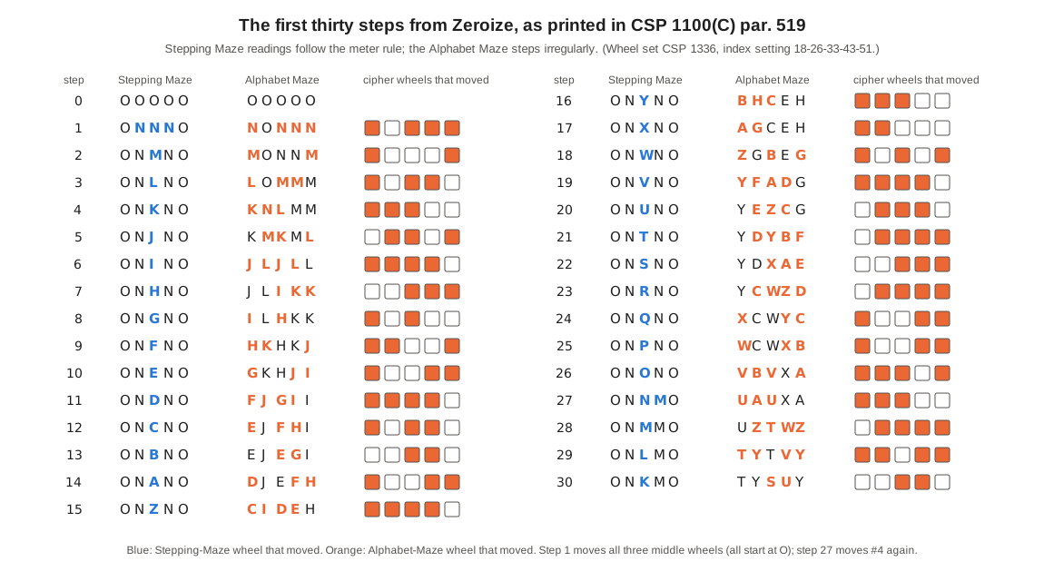
The first line of the table shows the start of every message: from the zeroize position all three middle wheels read O, so the first cycle moves all three (the manual warns repair crews of exactly this: “the first cycle will cause the stepping of all three center Code Wheels”). The Alphabet-Maze column shows the other half of the story. Its readings depend on the wirings of wheels C31 to C40, which have never been published, so they cannot be reproduced. What can be read from them is the motion: at every one of the thirty steps between one and four of the five wheels moved, each by exactly one letter, in the O-to-N direction of a normal wheel. That too is a self-test of the simulator.
4.4 Nine Bundles of Contacts
The four currents leave the Stepping Maze on four of its 26 left-hand contacts. These 26 are not led individually anywhere. They are wired in nine groups to nine of the ten input contacts of the Index Maze; the tenth input is not connected. Pekelney’s emulation, built from the Pampanito machine, gives the grouping for the CSP-889:
Table 1 — The four currents leave the Stepping Maze on four of its 26 left-hand contacts. These 26 are not led individually anywhere. They are wired in nine groups to nine of the ten input contacts of the Index Maze; the tenth input is not connected. Pekelney's emulation, built from the Pampanito machine, gives the grouping for the CSP-889
| Index input | Stepping-Maze contacts | Count |
|---|---|---|
| 1 | B | 1 |
| 2 | C | 1 |
| 3 | D E | 2 |
| 4 | F G H | 3 |
| 5 | I J K | 3 |
| 6 | L M N O | 4 |
| 7 | P Q R S T | 5 |
| 8 | U V W X Y Z | 6 |
| 9 | A | 1 |
| 0 | — | 0 |
Two or more currents can arrive in the same group; they then enter the Index Maze as one, which is one of the ways fewer than four wheels end up stepping.
At the far end of the Index Maze, its ten output contacts are joined in pairs to the five stepping magnets of the Alphabet Maze: outputs 0 and 9 to the magnet of cipher wheel 1, 7 and 8 to wheel 2, 5 and 6 to wheel 3, 3 and 4 to wheel 4, and 1 and 2 to wheel 5. Mucklow’s history describes the same arrangement: the index outputs “are bundled by adjacent pairs into five wires that connect to each one of the five cipher rotors” (Appendix B).
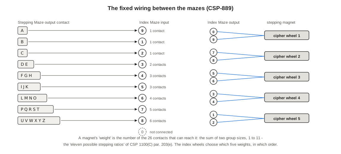
The uneven groups are deliberate. Each input of the Index Maze is reached by a different number of the 26 contacts, from none to six, and the Index Maze is a fixed permutation of its ten contacts, so each stepping magnet is reached through exactly two inputs. Call the number of Stepping-Maze contacts that can reach a magnet its weight: it is the sum of two group sizes, and since the sizes are 0, 1, 1, 1, 2, 3, 3, 4, 5 and 6, a weight can be any whole number from 1 to 11. The five weights always add to 26. This is what the manual means when it says “the Index Maze selects five out of eleven possible stepping ratios and assigns them to the Code Wheels in any one of 120 possible different ways” (par. 203(e)): setting the index wheels decides how heavily each cipher wheel is weighted, and which wheel gets which weight.
4.5 The Index Maze
The index wheels are like the code wheels but smaller, with ten contacts a side instead of 26 and no ratchet, “because it is not stepped by the machine; all setting must be done by hand” (par. 202(b)). Each is numbered by tens: the five in a machine were wheels 10, 20, 30, 40 and 50, and each wheel’s rim is engraved with its own ten numbers, so wheel 10 reads 10 to 19 and wheel 50 reads 50 to 59. A key list’s index setting such as 18-26-33-43-51 therefore says, in one string, both which wheel goes where and how it is turned: wheel 10 at 8, wheel 20 at 6, wheel 30 at 3, wheel 40 at 3, wheel 50 at 1. The key list normally gave a different index setting, with its own 26-30 check, for each secrecy classification of message (par. 303(e)).
The wheels were normally left in their slots and only turned, but a key list could call for a different order, in which case the spindle was pulled and the wheels rearranged by their tens digits (par. 303(e)(1)). According to Mucklow, the index wheels could physically be inserted reversed but “were placed forward throughout World War II”, their order was changed daily during most of the war, and from June 1945 the order stayed fixed and only the settings changed (Appendix A; Pekelney gives the same date for the SIGQZF-2 procedure).
Pekelney recorded the wirings of the five index wheels of the Pampanito machine, embossed “CTT 68AAC” on their edges: “We do not know when they served” (ECMApp source). They are the only real SIGABA wheel wirings in the public record, and the simulator uses them:
Table 2 — Pekelney recorded the wirings of the five index wheels of the Pampanito machine, embossed "CTT 68AAC" on their edges: "We do not know when they served" (ECMApp source). They are the only real SIGABA wheel wirings in the public record, and the simulator uses them
| Wheel | Contact 0 1 2 3 4 5 6 7 8 9 goes to |
|---|---|
| 10 | 7 5 9 1 4 8 2 6 3 0 |
| 20 | 3 8 1 0 5 9 2 7 6 4 |
| 30 | 4 0 8 6 1 5 3 2 9 7 |
| 40 | 3 9 8 0 5 2 6 1 7 4 |
| 50 | 6 4 9 7 1 3 5 2 8 0 |
How much variety do five such wheels give? There are 5! = 120 orders and 10^5 settings, twelve million in all. But what reaches the cipher wheels is only which magnet each of the nine live inputs ends at, and swapping the two outputs of any pair changes nothing. The number of different effects is therefore at most 10!/2^5 = 113,400, as Lasry pointed out (2019, section 1.2; Library copy). Running all twelve million settings of the Pampanito wheels through the simulator (sigaba_attack.py --index-space, fourteen seconds) shows that they produce 1,811,874 different permutations of the ten contacts, and that those include all 113,400 possible effects. The real wheels lose nothing to the bound. Volume 8 uses the figure.
4.6 Why One to Four
At least one cipher wheel steps on every letter: four currents enter the Stepping Maze, every one of the 26 contacts at its far end is wired to a live index input (only input 0 is idle, and nothing is wired to it), and every index output is wired to a magnet. At most four step, because there are only four currents. Between those limits the number varies with the coincidences of the moment: two currents in the same group, or two that leave the Index Maze on the two outputs of the same pair, fire one magnet between them.
Over 400 random keys and 80,000 letters, the simulator gives this distribution (sigaba_attack.py --stats):
Table 3 — Over 400 random keys and 80,000 letters, the simulator gives this distribution (sigabaattack.py --stats)
| Cipher wheels stepped | Share of letters |
|---|---|
| 1 | 1.1 % |
| 2 | 25.3 % |
| 3 | 56.7 % |
| 4 | 16.9 % |
On average 2.89 of the five wheels move after each letter. There are 30 possible stepping patterns (5 + 10 + 10 + 5 ways to choose one, two, three or four wheels), and the attacks of Volume 8 have to consider all 30 after every letter they test.
4.6.1 The CSP-2900
After the war, some machines were modified into the CSP-2900, and the Pampanito machine is one of them: built as a CSP-889 in June 1943, modified around 1950, with “one switch and a knob” to run as either (Pekelney). Pekelney’s emulation records three changes in 2900 mode: six contacts, D to I, are energized instead of four; the Stepping-Maze contacts P, Q and R are disconnected and U and V go to index input 0; and cipher wheels 2 and 4 step the opposite way. The simulator has a CSP-2900 mode built from that description. It has one surprise: with six live wires, all five cipher wheels step together on about 8 per cent of letters, the condition the 1944 patent warned against. Pekelney’s code comments say “between 1 and 4” but his code does not prevent five. Whether a real CSP-2900 ever stepped five wheels is unconfirmed; the rest of this unit uses the wartime CSP-889.
4.7 How Often Each Wheel Moves
The weights make it possible to predict how often each cipher wheel steps without running the machine. The four live contacts at the left end of the Stepping Maze behave like four different contacts drawn at random from 26. A magnet of weight w misses all four only if all four fall among the other 26 − w, so it fires with probability
1 − C(26 − w, 4) / C(26, 4).
On the demonstration key used throughout this unit, with the index wheels at 18-26-33-43-51, the five weights come out as 6, 5, 6, 5 and 4. The formula predicts that cipher wheels 1 and 3 step on 67.6 per cent of letters, wheels 2 and 4 on 60.0 per cent and wheel 5 on 51.1 per cent. Running the simulator for 10,000 letters from the zeroize position gives 68.4, 60.0, 67.1, 59.9 and 51.0 per cent.
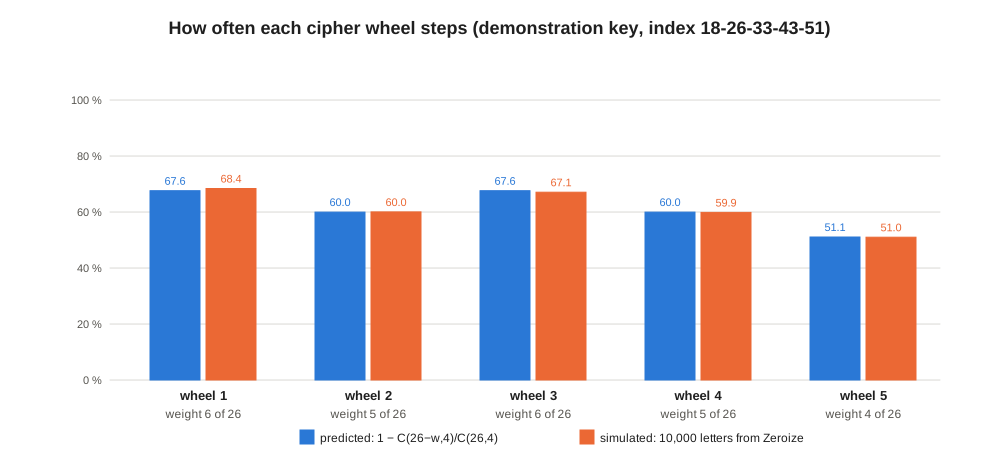
Two observations follow. Every cipher wheel moves often, more than half the time, so no wheel in the Alphabet Maze is ever a slow wheel that an analyst could treat as fixed over a stretch of text, as the slow rotor of an Enigma could be. And the rates differ from key to key in a way the analyst cannot know in advance, because they are set by the index wheels.
4.8 A Letter Wire by Wire
The demonstration key puts wheels 0, 1R, 2, 3, 4R in the Alphabet Maze, 5, 6, 7R, 8, 9 in the Stepping Maze, and the index wheels in order at 18-26-33-43-51. Set both code-wheel mazes to K M T B R (the joint Army-Navy method of Volume 5 does exactly this) and press A at E. The simulator’s trace (sigaba_sim.py --align KMTBR --trace A) follows the letter in three stages.
1. The Alphabet Maze. Wheel 0 at K takes A to Y; wheel 1, reversed, at M takes Y to Z; wheel 2 at T takes Z to Z; wheel 3 at B takes Z to S; wheel 4, reversed, at R takes S to Y. The printer prints Y (Volume 3 shows the same path).
2. The Stepping and Index Mazes. Current enters the right-hand end on F, G, H and I and passes through wheels 5, 4, 3, 2 and 1 in that order (the table heads give slot and wheel number):
Table 4 — 2. The Stepping and Index Mazes. Current enters the right-hand end on F, G, H and I and passes through wheels 5, 4, 3, 2 and 1 in that order (the table heads give slot and wheel number)
| In | 5: wheel 9 | 4: wheel 8 | 3: wheel 7R | 2: wheel 6 | 1: wheel 5 | Group | I10 | I20 | I30 | I40 | I50 | Magnet |
|---|---|---|---|---|---|---|---|---|---|---|---|---|
| F | G | A | I | C | H | 4 | 1 | 1 | 8 | 6 | 1 | 5 |
| G | N | U | F | K | N | 6 | 6 | 5 | 6 | 1 | 8 | 2 |
| H | R | D | N | M | E | 3 | 7 | 4 | 9 | 5 | 4 | 4 |
| I | K | P | K | G | Q | 7 | 0 | 6 | 4 | 8 | 9 | 1 |
The F current, for instance, leaves the Stepping Maze on contact H, which belongs to group F G H and so enters the Index Maze on input 4; the five index wheels carry it to output 1; outputs 1 and 2 are wired to the magnet of cipher wheel 5. The four currents reach four different magnets, 5, 2, 4 and 1.
3. The stepping. After the letter is printed, cipher wheels 1, 2, 4 and 5 step; wheel 3 does not. Wheel 1 (normal) goes from K to J, wheel 2 (reversed) from M to N, wheel 4 (normal) from B to A and wheel 5 (reversed) from R to S. In the Stepping Maze, wheel 3 always steps; it is reversed, so it goes from T to U. Wheel 3 did not read O, so wheel 4 stays put. The machine now reads JNTAS in the Alphabet Maze and KMUBR in the Stepping Maze, and the next letter starts from there.
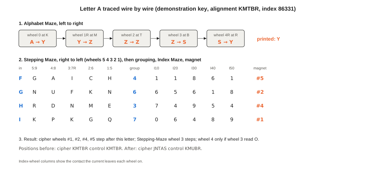
Every number in that trace is mechanical; none is chance. An operator with the same wheels, set the same way, gets the same four magnets, and a receiving machine, deciphering Y, sends Y through the Alphabet Maze the other way, gets A, and then fires the same four magnets, because the Stepping and Index Mazes do not care which way the cipher current went or what letter it was. That independence is what makes decipherment possible. Volume 8 shows it is also the machine’s one structural weakness.
4.9 The Navy Alignment
There is one moment when the two halves of the machine do interact: when the operator sets a message’s starting position by the Navy’s general method of 1944 (Volume 5). The operator zeroizes, sets the controller to R, and presses numeral key 1 until Stepping-Maze wheel 1 shows the first letter of the chosen alignment, then key 2 for wheel 2, and so on (par. 309). Each press steps one Stepping-Maze wheel by one letter, and the manual adds: “While the Code Wheels of the Stepping Maze are being aligned, the Code Wheels of the Alphabet Maze will also step.” Pekelney’s emulation does this the obvious way: each press first steps the cipher wheels as the Stepping and Index Mazes currently direct, then moves the chosen control wheel.
So the Alphabet Maze’s starting position is never chosen by anyone. It is the end of a short irregular walk from O that depends on the whole key and on the five letters. On the demonstration key, setting the Stepping Maze to KMTBR this way takes 47 presses (4, 2, 5, 13 and 23 for the five wheels; wheel 3 is reversed and counts up from O to T), and leaves the Alphabet Maze at I U F N K. The five letters went into the message in the clear, as the internal indicator, but without the key they say nothing about where the cipher wheels stand.
The manual adds a check: after aligning, look at the Alphabet Maze, and if all five of its wheels still read O, the stepping circuits are dead and the machine must not be used (par. 309(c)(4)). Volume 12 runs both methods in full.
4.10 What the Design Bought
Put together, the three mazes turn a five-wheel rotor machine into something else. The cipher wheels move irregularly, between one and four at a time, in a pattern produced by a second machine whose own wheels move like a meter, filtered through a third set of wheels that changes the odds. The stepping pattern depends on the key: change any of the ten Stepping- or Index-Maze settings and it changes completely. And unlike the Hagelin machines’ pins and lugs (M-209 unit, Volume 3) or the Enigma’s notches, nothing in the stepping is visible in the cipher text.
The price was paid in a different coin. The stepping decision is made entirely by the Stepping and Index Mazes; the Alphabet Maze only obeys it. An attacker who could guess the Alphabet Maze’s settings would need to know only which of 30 stepping patterns followed each letter, and could look for those patterns separately. That is the seam along which the modern attacks of Volume 8 split the machine. In 1944 no one had the computing power to exploit it, and the machine’s makers knew of no method that could.
Sources
- US Navy, ECM Operating Instructions, CSP 1100(C), 16 May 1944, paras 202-204, 303, 309, 511, 519 (stepping check table), transcribed by Richard Pekelney: maritime.org/doc/crypto/ecm.
- Richard Pekelney, ECMApp emulation source (1996-99), wiring tables and control-bank code: maritime.org/tech/ecmapp.txt; and “Electronic Cipher Machine (ECM) Mark II”: maritime.org/tech/ecm2.htm.
- L. F. Safford and D. W. Seiler, US Patent 6,175,625 B1 (Library copy), “Control Circuits for Electric Coding Machines” (filed 1944, granted 2001): patents.google.com/patent/US6175625B1.
- Timothy J. Mucklow, The SIGABA/ECM II Cipher Machine: “A Beautiful Idea” (Library copy), NSA Center for Cryptologic History, 2015, Appendices A-B: media.defense.gov.
- George Lasry, “A Practical Meet-in-the-Middle Attack on SIGABA”, HistoCrypt 2019: ep.liu.se/ecp/158/005 (Library copy).
Next — Volume 5: Keys, Key Lists and Procedure. The key list and the men who made it; zeroizing and the 26-30 letter check that every operator ran before every day’s work; the Navy’s and the Army’s two ways of setting a message; the external and internal indicators; and the one operating error that could turn the most secure machine of the war into a simple substitution.
Comments (0)