SIGABA · Volume 11
SIGABA — Volume 11 — Building a SIGABA II — Wiring, Controller and Verification
Three hundred and ten wires from ten tables, the two boards that carry the fixed wiring, the schematic and pin map, the controller's program in one machine cycle, and a bring-up in nine stages that ends with the replica agreeing with the Navy's own stepping table and with the simulator letter for letter
11.1 About This Volume
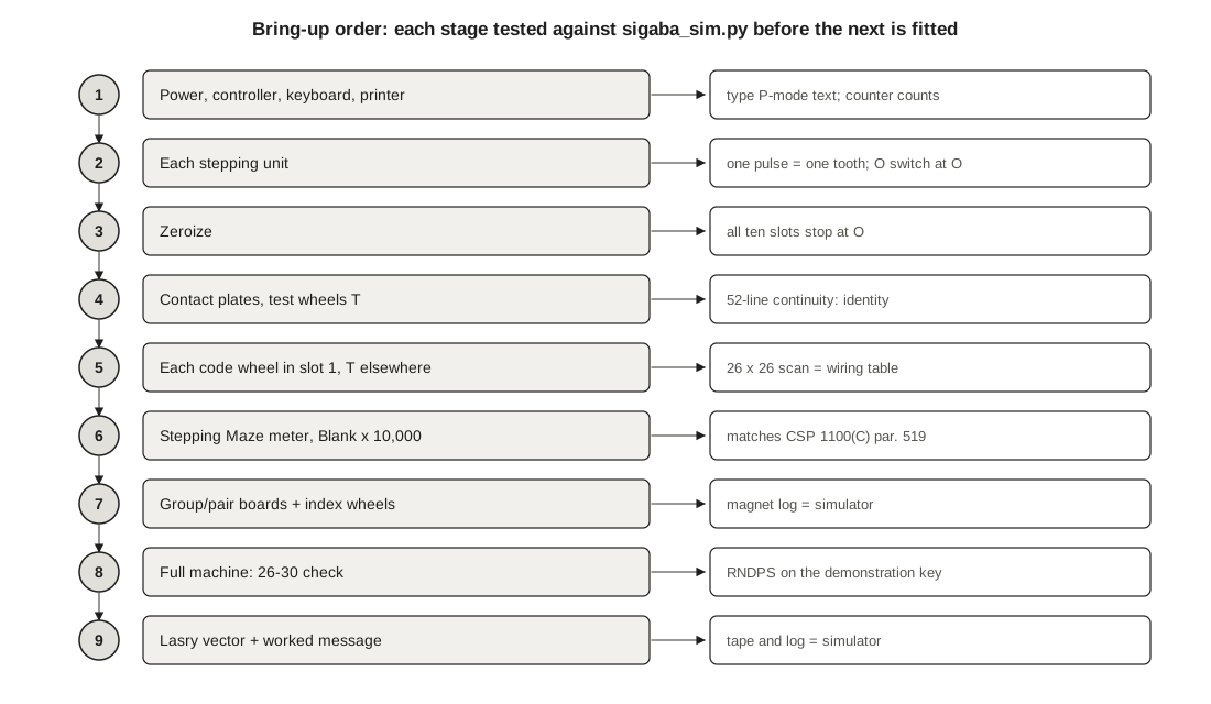
Volume 10 designed the replica and listed its parts. This volume puts it together and proves it. It covers the wiring of the fifteen wheels and the two fixed boards, the schematic and the allocation of every controller pin, the program that runs one machine cycle, and the bring-up: nine stages, each tested before the next part is fitted, each against a number that comes either from the Navy’s 1944 manual or from the unit’s simulator, 03-outputs/tools/sigaba_sim.py.
The simulator is the reference for the whole build, so it is worth knowing how far to trust it. Its self-test (python3 sigaba_sim.py --selftest) passes nine checks against published sources:
Table 1 — The simulator is the reference for the whole build, so it is worth knowing how far to trust it. Its self-test (python3 sigabasim.py --selftest) passes nine checks against published sources
| # | Vector | Source | What it proves |
|---|---|---|---|
| 1 | Twenty A’s enciphered from a stated key give JTSCALXDRWOQKRXHKMVD, and decipher back | George Lasry’s reference simulator, HistoCrypt 2019, Listing 1; itself compatible with Pekelney’s 1996 emulation and checked against Geoff Sullivan’s 2002 simulator | wheel paths, reversed wheels, the meter, grouping, index and pairs, order of operations |
| 2 | A 38-letter encipherment with spaces, on wirings unlike Pekelney’s | CyberChef’s SIGABA test suite (hettysymes, 2020) | the space-to-Z and Z-to-X rules; arbitrary wirings |
| 3-4 | A 1,000-letter encipherment and a 1,000-letter decipherment on Pekelney’s wirings | the same suite | long runs, including thousands of meter steps |
| 5 | All 56 Stepping-Maze readings, steps 0 to 10,000 from zeroize | CSP 1100(C), 1944, par. 519 | the meter rule, against the original’s own manual |
| 6 | The Alphabet-Maze readings of steps 0 to 30 move one to four wheels by one letter, the right way | the same table | the stepping direction and the one-to-four rule |
| 7 | Random keys: every CSP-889 cycle steps one to four wheels; decipherment inverts encipherment | structural | no hidden asymmetry |
Lasry’s code and CyberChef’s are independent of each other and of this simulator, so passing both is a cross-check of three implementations; the manual’s table is a check against the machine itself. The one thing no test can supply is the wartime wheel wirings, which have never been published (Volume 3). The replica therefore uses the same simulated wirings as the simulator, and the build is verified when the two agree.
11.2 The Wheel Wiring Tables
Each code wheel’s wiring is one line of the simulator’s WIRINGS table, Pekelney’s simulated set. Read it as: pad i on the left face is wired to the pad named in column i on the right face.
Table 2 — The Wheel Wiring Tables
| Wheel | A B C D E F G H I J K L M N O P Q R S T U V W X Y Z |
|---|---|
| 0 | Y C H L Q S U G B D I X N Z K E R P V J T A W F O M |
| 1 | I N P X B W E T G U Y S A O C H V L D M Q K Z J F R |
| 2 | W N D R I O Z P T A X H F J Y Q B M S V E K U C G L |
| 3 | T Z G H O B K R V U X L Q D M P N F W C J Y E I A S |
| 4 | Y W T A H R Q J V L C E X U N G B I P Z M S D F O K |
| 5 | Q S L R B T E K O G A I C F W Y V M H J N X Z U D P |
| 6 | C H J D Q I G N B S A K V T U O X F W L E P R M Z Y |
| 7 | C D F A J X T I M N B E Q H S U G R Y L W Z K V P O |
| 8 | X H F E S Z D N R B C G K Q I J L T V M U O Y A P W |
| 9 | E Z J Q X M O G Y T C S F R I U P V N A D L H W B K |
Three conventions make a hand-wired wheel agree with the simulator, and all three come from Pekelney’s emulation:
- Pads with the same letter sit directly opposite each other through the wheel. Pad A of the left face is behind pad A of the right face.
- The left face is the face that is on the left when the wheel is inserted normally. Its silkscreen carries the wheel number; the right face carries the alphabet, as the originals’ engraved face did.
- Each letter on the rim sits radially outside the pad of the same letter, and the reference line marks contact position A. The letter at the reference line is then the wheel’s position in the simulator: when wheel 0 reads K, pad K is at contact A.
The stepping direction follows: the pawl must push the wheel so that its reading goes down the alphabet, O to N, when the wheel is normal (Volume 3).
The index wheels are wired the same way from the Pampanito table in Volume 4. Index pads are numbered 0 to 9 on both faces, and the rim carries the wheel’s own numbers: wheel 30’s rim reads 30 to 39, with 30 radially outside pad 0.
11.2.1 Method
The work is 260 wires for the code wheels, 50 for the index wheels and 104 for the four test wheels, which are wired straight across, A to A.
- Cut 26 lengths of 30 AWG wire-wrap wire, 70 mm long, in two colours: one colour for A to M on the left face, another for N to Z, which makes errors easier to see.
- Solder all 26 to the inside pads of the left face-plate first, and fit it to the body. Then thread each wire round the annular channel to its right-face pad, working down the table with a printed copy and ticking each wire off. Solder the right face-plate’s pads one at a time, then close the wheel.
- Test before closing. With a meter on continuity, check each left pad against the right pad the table names, and that it reaches no other. A wheel with a crossed pair passes the 26-30 check of no key it is in.
11.3 The Group and Pair Boards
The basket’s two fixed boards carry the only wiring that is the same in every SIGABA. The group board joins the 26 left-hand contacts of the Stepping Maze to nine inputs of the Index Maze; the pair board joins the Index Maze’s ten outputs to five magnet lines. Both are drawn straight from the simulator’s CONTROL_TO_INDEX and INDEX_TO_MAGNET tables (Volume 4 gives them as tables).
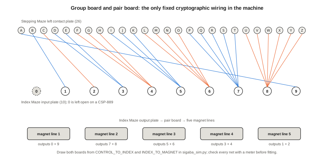
Check every net with a meter before fitting: A to index input 9 and to nothing else; D and E together to input 3; U through Z together to input 8; and so on. An error here is the one fault that the 26-30 check may not find quickly, because it changes the odds of stepping without stopping it.
11.4 The Schematic and Pin Map
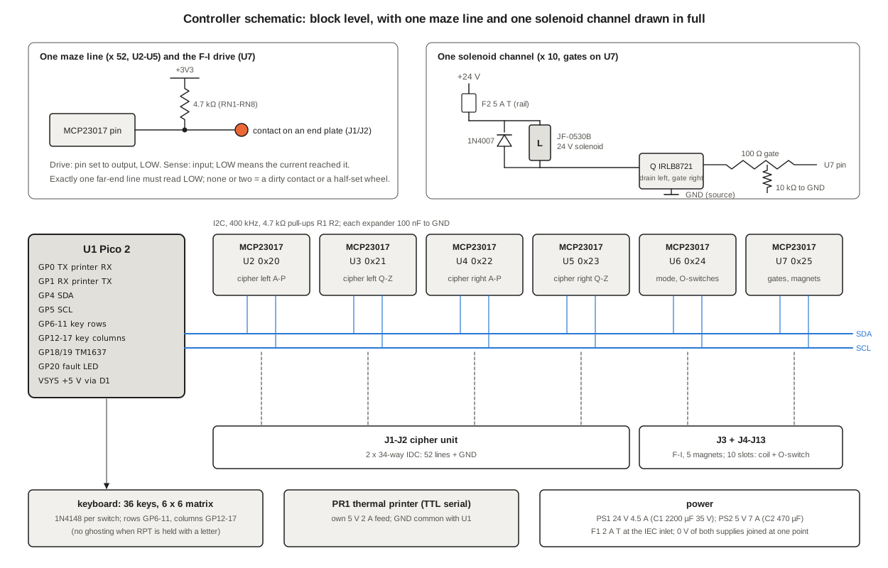
The schematic at the head of this volume shows the controller at block level, with one maze line and one solenoid channel drawn in full. The pin map:
Table 3 — The schematic at the head of this volume shows the controller at block level, with one maze line and one solenoid channel drawn in full. The pin map
| Device | Pins | Connected to |
|---|---|---|
| U1 Pico 2 | GP0, GP1 | printer PR1 RX, TX (UART0, 19,200 baud) |
| GP4, GP5 | I2C0 SDA, SCL; R1, R2 4.7 kΩ to 3.3 V | |
| GP6-GP11 | keyboard rows (outputs) | |
| GP12-GP17 | keyboard columns (inputs, pull-down); diode D12-D47 per key | |
| GP18, GP19 | TM1637 counter display DS1, CLK and DIO | |
| GP20 | fault LED1 via R23 | |
| GP21 | counter reset button S13 | |
| U2 MCP23017 0x20 | GPA0-7, GPB0-7 | Alphabet Maze left contacts A-P (J1) |
| U3 0x21 | GPA0-7, GPB0-1 | Alphabet Maze left contacts Q-Z (J1) |
| U4 0x22 | GPA0-7, GPB0-7 | Alphabet Maze right contacts A-P (J2) |
| U5 0x23 | GPA0-7, GPB0-1 | Alphabet Maze right contacts Q-Z (J2) |
| U6 0x24 | GPA0-4 | controller S11: O, P, R, E, D (internal pull-ups) |
| GPA5 | zeroizer S12 | |
| GPA6, GPA7 | O-switches, Stepping slots 4 and 5 | |
| GPB0-4 | O-switches, Alphabet slots 1-5 | |
| GPB5-7 | O-switches, Stepping slots 1-3 | |
| U7 0x25 | GPA0-4 | gates Q1-Q5: solenoids, Alphabet slots 1-5 |
| GPA5-7, GPB0-1 | gates Q6-Q10: solenoids, Stepping slots 1-5 | |
| GPB2 | common F-I drive to the Stepping Maze’s right-hand end plate (J3) | |
| GPB3-7 | magnet lines 1-5 from the pair board (J3) |
Each of the 52 Alphabet-Maze lines and the five magnet lines has a 4.7 kΩ pull-up to 3.3 V in a bussed network (RN1-RN8). The F, G, H and I contacts of the Stepping Maze’s right-hand end plate are joined on the plate and brought out as one line: the four currents are applied together, as on the original. The 24 V rail is fused at 5 A (F2) and has C1, 2,200 µF, at the driver board; every solenoid has its 1N4007 at the coil, not at the board.
11.5 The Controller’s Program
The program is MicroPython on the Pico. Most of it is housekeeping: scanning the keyboard, reading the controller and zeroizer switches, the counter display and the printer. The heart is one function that does what one turn of the original’s main shaft did (Volume 3): cipher current first, stepping current second, stepping last.
def cycle(key, decipher=False, blank=False):
    out = None
    if not blank:                          # 1. the cipher current
        src, dst = (RIGHT, LEFT) if decipher else (LEFT, RIGHT)
        drive_low(src, key)                # one line low, the rest inputs
        lows = read_lows(dst)              # lines pulled low through the wheels
        release(src)
        if len(lows) != 1:
            return fault("maze", lows)     # dirty contact or a half-set wheel
        out = lows[0]
    fi_drive_low()                         # 2. the stepping current
    mags = [m for m in range(5) if magnet_low(m)]
    fi_release()
    if not mags:
        return fault("no stepping")        # would be a simple substitution
    o3, o4 = o_switch(STEP, 3), o_switch(STEP, 4)   # read before anything moves
    slots = [(ALPH, m + 1) for m in mags] + [(STEP, 3)]
    if o3:
        slots.append((STEP, 4))
        if o4:
            slots.append((STEP, 2))
    pulse(slots, ms=25)                    # 3. the wheels move
    sleep_ms(40)                           # detents settle
    count_up()
    log(key, out, mags)                    # same format as sigaba_sim.py --log
    return out
Around it, the controller and zeroizer positions select the behaviour CSP 1100(C) par. 208 gives each (Volume 3): at E, a letter key calls cycle after the word-spacer substitution (space becomes Z, Z becomes X) and the result is printed in groups of five; at D, the result is printed with Z as a space; at R with the zeroizer at Operate, numeral key k steps the Alphabet Maze as the stepping current directs and then pulses Stepping slot k alone (Pekelney’s reading of par. 309); at R with the zeroizer at Zeroize, holding BLANK and RPT pulses every slot whose O-switch is open until all ten are closed; and at P the machine types plain text. BLANK at E or D runs a cycle without printing.
Two departures from the original are deliberate. The replica refuses to print when the maze reads no line or two lines, or when no stepping current gets through; the original printed whatever the wheels gave, and the 26-30 check caught it afterwards. And it accepts keystrokes over its USB serial port as well as from the keyboard, so that long test vectors can be fed in without typing them. Every cycle writes a log line in the simulator’s format:
0001 X V 1245which reads: counter 1, the machine enciphered X (the Z key), printed V, and fired the magnets of cipher wheels 1, 2, 4 and 5. A log from the replica and the same command run on the simulator can be compared with diff.
11.6 Bringing It Up
11.6.1 Controller, keyboard and printer
With no basket and no solenoids connected, power the controller. At P, every key should print its own character, the space bar a space, and the counter should count each stroke. Check every key; a diode fitted backwards shows as a key that does nothing or as two keys at once.
11.6.2 Each stepping unit
Connect one stepping unit at a time and fit a single code wheel over it on a test spindle. One pulse must turn the wheel exactly one letter, in the direction that takes a normal wheel from O to N; the detent must centre it; and the O-switch must close only at O, whichever way round the wheel is fitted. Adjust the pawl stop until fifty pulses move the wheel exactly fifty letters. This is the stage at which a printed ratchet shows its wear; replace it with a brass one if a tooth rounds.
11.6.3 Zeroize
With all ten slots filled, set R and Zeroize and hold BLANK and RPT. Every wheel must stop at O within 25 pulses and stay there.
11.6.4 Contact plates and test wheels
Fit the four test wheels and one more test wheel in the Alphabet Maze, so that all five are straight-through. At any positions, driving each of the 26 left-hand lines must pull low exactly the right-hand line of the same letter: A to A, B to B. A line that reads nothing is an open pin; two lines is a short on a plate. Then drive from the right and read the left.
11.6.5 Each code wheel
Put the wheel under test in slot 1 of the Alphabet Maze and test wheels in slots 2 to 5. The firmware’s scan command drives all 26 lines in turn without stepping and prints the substitution; sigaba_sim.py --scan prints what it should be. For wheel 0, normal, at A:
Table 4 — Put the wheel under test in slot 1 of the Alphabet Maze and test wheels in slots 2 to 5. The firmware's scan command drives all 26 lines in turn without stepping and prints the substitution; sigabasim.py --scan prints what it should be. For wheel 0, normal, at A
| In | A B C D E F G H I J K L M N O P Q R S T U V W X Y Z |
|---|---|
| Wheel 0 at A | Y C H L Q S U G B D I X N Z K E R P V J T A W F O M |
| Wheel 0 at O | W Q D B H V F M I R A Y K O T X C E G S N P U J Z L |
| Wheel 0 reversed, at A | F N A P E I U G V K W J C O B X M H Q Y T D L R Z S |
At A, a normal wheel shows its own wiring line; at any other position, and reversed, it shows a substitution that only the simulator can predict. A wheel that matches at A but not reversed has its faces’ pad labels mirrored; one that matches nowhere has crossed wires. Every wheel is scanned at A and at O, both ways round, in slot 1; then the five Stepping-Maze slots are checked the same way by moving the wheel there with test wheels around it (the controller can drive the Stepping Maze’s right-hand end line by line for this test through the F-I line and a jumper plug).
11.6.6 The Stepping Maze meter
This is the test the Navy gave its own repair crews (CSP 1100(C) par. 519), and it does not depend on any wiring. Zeroize, set E and Operate, reset the counter, and step with BLANK and RPT, stopping at the step numbers in the table. The Stepping Maze, with all five wheels normal, must read:
Table 5 — This is the test the Navy gave its own repair crews (CSP 1100(C) par. 519), and it does not depend on any wiring. Zeroize, set E and Operate, reset the counter, and step with BLANK and RPT, stopping at the step numbers in the table. The Stepping Maze, with all five wheels normal, must read
| Step | 0 | 1 | 2 | 14 | 15 | 26 | 27 | 40 | 100 | 700 | 1,000 | 10,000 |
|---|---|---|---|---|---|---|---|---|---|---|---|---|
| Stepping Maze | OOOOO | ONNNO | ONMNO | ONANO | ONZNO | ONONO | ONNMO | ONAMO | ONSKO | OMQNO | OMCBO | OZYTO |
These twelve are a selection from the manual’s 56 readings, all of which the simulator reproduces. Running the full 10,000 steps takes about eleven minutes at the replica’s 65 ms a cycle; it exercises wheel 3’s meter contact 385 times and moves the slow wheel 15 times. The Alphabet Maze’s readings in the manual’s table cannot be checked, because they depend on the wartime wheel set; but at every step one to four of its wheels must move.
11.6.7 Group and pair boards, and the index wheels
Fit the demonstration key of the unit: Alphabet Maze 0, 1R, 2, 3, 4R; Stepping Maze 5, 6, 7R, 8, 9; index wheels 10, 20, 30, 40, 50 at 18-26-33-43-51. Zeroize, set E, and step with BLANK, watching the log’s magnet column. It must read, from step 0:
Table 6 — Fit the demonstration key of the unit: Alphabet Maze 0, 1R, 2, 3, 4R; Stepping Maze 5, 6, 7R, 8, 9; index wheels 10, 20, 30, 40, 50 at 18-26-33-43-51. Zeroize, set E, and step with BLANK, watching the log's magnet column. It must read, from step 0
| Step | 0 | 1 | 2 | 3 | 4 | 5 | 6 | 7 | 8 |
|---|---|---|---|---|---|---|---|---|---|
| Magnets fired | 2345 | 1234 | 1245 | 35 | 123 | 135 | 145 | 145 | 345 |
| Alphabet Maze after | OPNNP | NQMMP | MRMLQ | MRLLR | LSKLR | KSJLS | JSJKT | ISJJU | — |
(sigaba_sim.py --steps 8 prints the same table.) A wrong magnet number with right stepping counts points to the pair board; wrong counts point to the group board or an index wheel.
11.6.8 The 26-30 letter check
Zeroize; set E; step 25 times with BLANK; encipher A five times. The demonstration key at the SECRET index setting 18-26-33-43-51 must print RNDPS, and at 15-24-31-47-52 ZJRBA (Volume 5 and Volume 12). Then set one index wheel deliberately half-way between two numbers: the firmware reports “no stepping”; with the check disabled, the machine prints UUUUU, five alike letters, which the manual forbade an operator ever to accept (par. 308(d)).
11.6.9 Published vectors and a message
Set up Lasry’s reference key: Alphabet Maze 0R, 1, 2, 3, 4R set by hand to A B C D E; Stepping Maze 5, 6, 7R, 8, 9 set to F G H I J; index wheels 10, 20, 30, 40, 50 at 0, 1, 2, 3, 4. Encipher twenty A’s. The tape must read
JTSCA LXDRW OQKRX HKMVD
and deciphering it on the same settings must give twenty A’s. Then feed the two 1,000-letter CyberChef vectors (03-outputs/tools/sigaba_vectors.json) over the USB port and compare. Finally, encipher and decipher the worked message of Volume 12 and compare the replica’s log with sigaba_sim.py --align KMTBR --log "...". When those agree, the replica is a SIGABA in every sense that can be tested without a wartime wheel set.
11.7 Faults and What They Mean
Table 7 — Faults and What They Mean
| Symptom | Most likely cause |
|---|---|
| A key prints nothing, fault LED lit, “maze: []“ | an open contact: a pin not touching a pad, a dirty pad, a broken wire inside a wheel |
| ”maze: [two lines]“ | a short between adjacent pads or pins, or two wires crossed in a wheel |
| ”no stepping” | an index wheel between positions; a missing F-I connection; group board open |
| 26-30 check wrong by one or two letters | a wheel one letter off after zeroizing (cam-lobe or O-switch adjustment) |
| 26-30 check entirely wrong | wrong wheel, wrong slot or wrong way round; index setting wrong |
| decipherment right for a few letters, then garbage | a dropped or doubled step: pawl overshooting or a weak solenoid pulse (Volume 12 shows the effect of a lost letter) |
| meter test wrong at step 27 or 677 | O-switch of Stepping slot 3 or 4 closing at the wrong letter |
The original’s manual gives the same list in its own terms: dirty contacts, an index wheel “set half-way”, zeroizing springs out of adjustment, a broken cam-lobe (CSP 1100(C) paras 506-511).
Sources
- US Navy, ECM Operating Instructions, CSP 1100(C), 16 May 1944, paras 208, 212, 306-309, 506-519: maritime.org/doc/crypto/ecm.
- Richard Pekelney, ECMApp emulation source, 1996-99 (wiring tables, conventions, Reset-key behaviour): maritime.org/tech/ecmapp.txt.
- George Lasry, “A Practical Meet-in-the-Middle Attack on SIGABA”, HistoCrypt 2019, Listing 1: ep.liu.se/ecp/158/005 (Library copy).
- CyberChef SIGABA operation and tests (hettysymes, 2020, Apache-2.0): github.com/gchq/CyberChef.
- The unit’s simulator and tools:
03-outputs/tools/sigaba_sim.py,sigaba_vectors.json,sigaba_attack.py.
Next — Volume 12: Running SIGABA — Setting a Key, a Worked Message, and an Attack Demo. A key list for the day, the 26-30 check, a message enciphered by the joint Army-Navy method from indicator to tape and deciphered at the other end, the Navy method with its numeral keys, what a lost letter and a half-set index wheel do to a message, and a known-plaintext attack that recovers a message setting in nine seconds — given the key list.
Comments (0)