SIGABA · Volume 3
SIGABA — Volume 3 — How It Works I — The Cipher Bank, Keyboard and Printer
Fifteen wheels in a removable basket, the five that actually encipher, why every one of them could be turned round, what happened to the letter Z, and one turn of the main shaft from key to printed tape
3.1 About This Volume
Volumes 1 and 2 told what the SIGABA was and how the Army and Navy came to build it. This volume and the next take the lid off. The machine divides cleanly into two halves, and the division is the whole idea of the design. One half, the Alphabet Maze of five code wheels, does the enciphering: a letter goes in at one end and a different letter comes out at the other. The other half, the Stepping Maze and Index Maze, never touches the message at all; its only job is to decide, letter by letter, which wheels of the Alphabet Maze move. This volume covers the first half and everything the operator touches: the code wheels themselves, the path of a letter through them, the keyboard, the printer, the controller and zeroizer, and the cycle of the main shaft. Volume 4 covers the second half.
The primary source throughout is the Navy’s ECM Operating Instructions, CSP 1100(C), dated 16 May 1944, which Richard Pekelney transcribed for the USS Pampanito museum (maritime.org/doc/crypto/ecm); paragraph numbers below are that manual’s. The Navy called the machine the ECM Mark 2 and its rotors “code wheels”; the Army called the same parts “cipher rotors”, “control rotors” and “index rotors”. This volume uses the Navy’s words, because they are the words of the manual, with the Army’s in brackets where it helps.
Every enciphered example comes from the unit’s simulator, 03-outputs/tools/sigaba_sim.py, which reproduces a published reference encipherment by George Lasry, three published CyberChef test vectors and the 10,000-step stepping table printed in CSP 1100(C) itself (Volume 11 describes the tests). One limitation has to be stated at the start and will recur: no wartime code-wheel wiring has ever been published. The ten wheel wirings in the simulator are the simulated set Pekelney generated for his 1996 emulation; every SIGABA simulator since has used them. The index-wheel wirings, by contrast, are real, read from the wheels of the Pampanito machine. The examples therefore show exactly how the machine worked, letter by letter, but not what any wartime message actually looked like.
3.2 The Machine on the Bench
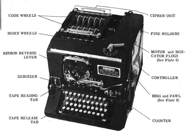
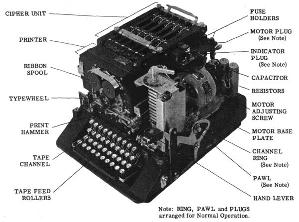
The ECM Mark 2 is an electric typewriter with a cipher on top. In working order it stood about 15 inches high, 19¼ inches wide and 12 inches deep and weighed about 93½ lb; in its carrying case it was 133½ lb (Pekelney, “Electronic Cipher Machine (ECM) Mark II”, from the Army Security Agency’s 1948 summary). The base holds a motor, a main shaft with its cams, a keyboard and a printer. On top sits a removable box of wheels, the cipher unit, CSP 887, which the Army called the rotor cage or basket.
CSP 1100(C) par. 201 lists the parts in order: code wheels and index wheels; cipher unit; code wheel stepping assembly; keyboard; printer; zeroizer; controller; electric motor; main shaft; emergency hand drive lever; automatic word spacer; counter; spark suppressors; input and output receptacles. Teletype Corporation of Chicago engineered the production machine for the Navy and built it, which is why the printer, the keyboard contacts and the cam-driven main shaft look like teleprinter practice (Pekelney). By 1943 about 10,060 had been bought at roughly $2,040 each. The first 651, the CSP 888, lacked the plugs for tandem operation; the rest, the CSP 889, had them (Volume 2 tells the history).
3.3 Three Rows of Wheels
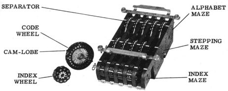
The cipher unit holds fifteen wheels in three rows of five (par. 203):
Table 1 — The cipher unit holds fifteen wheels in three rows of five (par. 203)
| Row (from the back) | Navy name | Army name | Wheels | Contacts | Moves? |
|---|---|---|---|---|---|
| Rear | Alphabet Maze | cipher rotors | code wheels | 26 each side | 1 to 4 of the 5 step on every letter |
| Middle | Stepping Maze | control rotors | code wheels | 26 each side | centre wheel every letter; two others like a meter |
| Front | Index Maze | index rotors | index wheels | 10 each side | never; set by hand |
The two kinds of 26-contact wheel are physically identical. A machine was issued ten code wheels, and the key list said which five went into the Alphabet Maze and which five into the Stepping Maze, in what order, and which way round. The index wheels are smaller and are a separate set of five. Both mazes of code wheels sit on spindles in a frame of separators, plates with through-contacts between each pair of wheels, and the whole unit lifts out by two handles once four thumb screws are loosened (par. 203(b)). The removable unit had three stated purposes: safe stowage of all the secret elements in one box, quick change from one system to another when a second unit was available, and “emergency disposition overboard” (par. 203(b)(1)). The machine without its wheels was classified CONFIDENTIAL; the wheels were SECRET.
3.4 The Code Wheel
CSP 1100(C) par. 202 describes the code wheel exactly. It consists of a steel ratchet, two face-plates, and the wiring that joins the contacts of one face-plate to the contacts of the other.
- The ratchet has 26 teeth. It is what the stepping pawl pushes when the machine steps the wheel, and it is also the detent: spring-loaded detent rollers drop between its teeth and hold the wheel squarely in one of its 26 positions.
- Each face-plate carries 26 contacts. One face-plate is engraved round its edge with the alphabet, for setting the wheel by eye; the other is engraved with the wheel’s identifying number. Inside, 26 wires join the 26 contacts of one face to the 26 of the other “at random”, in the words of the 1944 patent application: “such as A on one face to M on the other, B on one to G on the other” (US Patent 6,175,625, filed 15 December 1944, granted 16 January 2001; Library copy).
- Each face-plate has a cam-lobe, a projection on its rim between the engraved letters U and V. The cam-lobe stops the wheel at O when the machine zeroizes, and on the centre wheels of the Stepping Maze it closes the contacts that make the next wheel step (Volume 4).
The contacts on the face-plates are flat; the springs that press against them belong to the separators, not to the wheels. That detail is the key to one of the machine’s most valuable features. A Hebern or Enigma rotor has spring pins on one face and flat contacts on the other, so it fits into its machine only one way round. A SIGABA wheel has flat contacts on both faces, so either face can go to the left. The key list could therefore order any wheel inserted reversed, “with the engraved alphabet letters appearing upside down to the operator” (par. 303(d)(2)).
The ten code wheels of a set carried two-digit numbers. The manual’s own stepping check, for instance, uses the set published as CSP 1336, wheels C31 to C40, and a sample key list in the manual reads 31, 40, 32R, 39, 37 for the Alphabet Maze (par. 519; par. 303(c)). The wheels themselves were wired by hand, much of the work done by women of the Army’s and Navy’s cryptographic services (Volume 2), and sets were changed periodically and at once on any suspicion of compromise.
3.5 Following a Letter Through the Alphabet Maze
When the operator presses a letter key with the controller at E (encipher), a current enters the left-hand end of the Alphabet Maze on the contact for that letter, passes through the five code wheels in turn and leaves the right-hand end on one of 26 contacts, each wired to one magnet of the printer. Each wheel substitutes one letter for another, and the substitution each wheel makes depends on its wiring and on how far it is turned. Five wheels in series make one substitution of 26 letters, which changes whenever any of them moves.
The simulator follows Pekelney’s description of this exactly. A wheel at position p (the letter showing at the reference line, counted A = 0) receives a current on fixed contact c. The wheel’s own contact under c is number c + p; the wire inside takes it to the wheel’s contact w(c + p) on the other face; and that contact sits opposite fixed contact w(c + p) − p (everything mod 26). Deciphering runs the inverse wiring in the opposite direction. A reversed wheel uses the inverse wiring and counts its positions the other way.
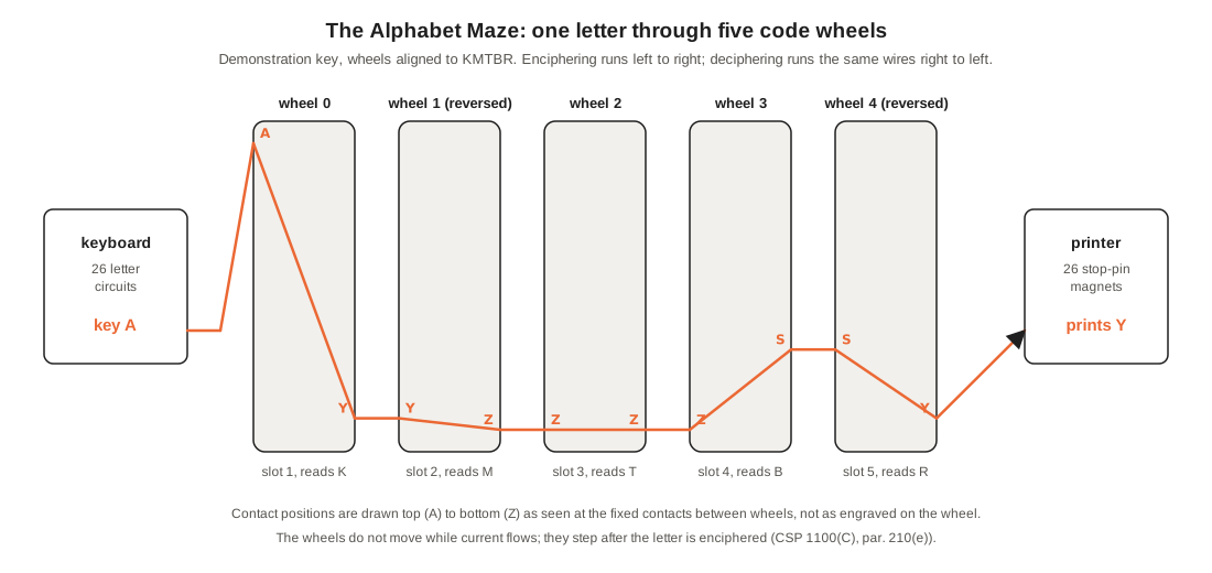
Take the demonstration key used in every worked example of this unit: Alphabet Maze wheels 0, 1R, 2, 3, 4R (wheel 1 and wheel 4 reversed), aligned to K M T B R. The simulator traces the letter A like this:
Table 2 — Take the demonstration key used in every worked example of this unit: Alphabet Maze wheels 0, 1R, 2, 3, 4R (wheel 1 and wheel 4 reversed), aligned to K M T B R. The simulator traces the letter A like this
| Slot | Wheel | Reads | Enters on | Leaves on |
|---|---|---|---|---|
| 1 | 0 | K | A | Y |
| 2 | 1 reversed | M | Y | Z |
| 3 | 2 | T | Z | Z |
| 4 | 3 | B | Z | S |
| 5 | 4 reversed | R | S | Y |
The printer prints Y.
With the wheels standing still at KMTBR, the whole alphabet enciphers as
Table 3 — Following a Letter Through the Alphabet Maze
| Plain | A B C D E F G H I J K L M N O P Q R S T U V W X Y Z |
|---|---|
| Cipher | Y F P N Z H S R E U D G I B T M Q X O A J L K V W C |
Three things about this table matter for everything that follows.
It is not reciprocal. A enciphers to Y, but Y enciphers to W. The Enigma sent its current through a reflector and back, which made every substitution a set of thirteen swapped pairs, so that the same setting enciphered and deciphered. The SIGABA has no reflector: the current goes straight through. Deciphering therefore needs the current to go the other way, entering at the right-hand end and leaving at the left, which the controller arranges by swapping which end of the maze is connected to the keyboard and which to the printer. The 1944 patent describes exactly this: the printer is “connected to the end of the code wheel maze opposite the end to which the keyboard is connected in both cases” (US 6,175,625, abstract; Library copy).
A letter can encipher to itself. In the table, Q enciphers to Q. The Enigma’s reflector made that impossible, and the Bletchley Park codebreakers used the gap mercilessly to place cribs (Enigma unit, Volumes 9 and 10). In the simulator, enciphering 26,000 random letters on the demonstration key produced 985 letters that came out as themselves, 3.8 per cent, almost exactly the 1 in 26 a random substitution would give. A SIGABA cipher text gives away nothing by what it lacks.
Any single wheel’s substitution is visible in this table only through all five. An attacker who could observe the table at two successive letters would see it change by an unknown amount in an unknown combination of wheels. That is the problem Volume 8 returns to.
3.6 Reversed Wheels
Turning a wheel round does two things. It presents the wiring backwards, so a single wheel offers two different substitutions; and it makes the wheel count the other way. A normal wheel, stepped by the machine, moves so that its reading goes down the alphabet, from O to N to M; a reversed wheel, driven by the same pawl in the same direction, shows its upside-down letters going up the alphabet, from O to P to Q. The simulator follows Pekelney’s emulation on both points, and the Stepping Maze readings that the machine is required to show in the manual’s stepping check (Volume 4) confirm the direction for normal wheels: from the zeroize position the centre wheel reads O, N, M, L and so on.
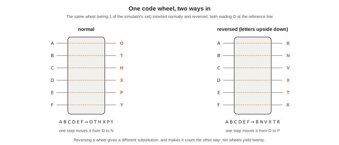
The cryptographic value is simple arithmetic. Ten wheels in ten slots can be arranged 10! = 3,628,800 ways; with each wheel normal or reversed there are 1,024 times as many, as if the set held twenty wheels. Volume 8 does the full count. The practical value was nearly as great: an operator could set up a new arrangement in a minute by lifting wheels off their spindles and dropping them back in another order or the other way round.
3.7 Encipher, Decipher and the Missing Z
The ECM was designed so that the plain text came out of the decipherment properly spaced, with words separated as the sender typed them. The device that achieves this is the automatic word spacer (par. 212):
- With the controller at E, the Z key’s contact is wired in parallel with the X key’s, and the space bar is connected to the Z circuit. Pressing Z enciphers an X; pressing the space bar enciphers a Z.
- With the controller at D, the printer’s Z circuit is connected not to the Z type but to a print-suppression magnet. A deciphered Z prints as a space.
The result is a plain text with its word breaks restored, at the price of the letter Z. The manual is cheerful about it: deciphered words “will be spelled with an X instead of a Z. Example: XERO, XE BRA, etc.” The patent application put the reasoning more plainly: “the letter Z is so seldom used, and the substitution of X for it is so obvious in the words where it occurs, that no difficulty arises.”
The simulator does the same. On the demonstration key at KMTBR, “ZERO HOUR” enciphers letter by letter like this (the third column is the cipher letter; the fourth is the set of cipher wheels that step afterwards, which Volume 4 explains):
Table 4 — The simulator does the same. On the demonstration key at KMTBR, "ZERO HOUR" enciphers letter by letter like this (the third column is the cipher letter; the fourth is the set of cipher wheels that step afterwards, which Volume 4 explains)
| Count | Key pressed | Machine enciphers | Prints | Wheels then stepped |
|---|---|---|---|---|
| 1 | Z | X | V | 1 2 4 5 |
| 2 | E | E | X | 1 3 4 5 |
| 3 | R | R | A | 1 2 4 5 |
| 4 | O | O | E | 1 2 3 |
| 5 | space | Z | P | 3 4 5 |
| 6 | H | H | M | 1 3 |
| 7 | O | O | H | 3 4 |
| 8 | U | U | C | 1 2 4 |
| 9 | R | R | M | 1 2 3 4 |
and the receiving machine, set the same way, prints XERO HOUR. Because the space is enciphered like any letter, the cipher text shows no word lengths, and because the cipher text is printed in groups of five regardless, it shows nothing of the message’s shape at all. Operators were told to spell out numerals and to use X for punctuation, keeping punctuation “at a minimum” (par. 311).
A decipherment that comes out with no spaces, or with spaces in strange places, is itself a diagnostic: the Z of the cipher alphabet is falling on the wrong letters, which means the machine is not set as the sender’s was.
3.8 The Keyboard
The keyboard is laid out like a typewriter’s, with the alphabet, the numerals, a dash and a space bar, and two extra keys: BLANK, which steps the machine through a full ciphering cycle without printing, and RPT, which makes any other key repeat for as long as it is held, and which must be pressed first (par. 205). The numeral keys 1 to 5 have a second set of contacts, used only when the controller is at R to step the wheels of the Stepping Maze one at a time while setting a message’s alignment (Volume 5 and Volume 4).
The keys do not move anything mechanically. Each closes an electrical contact in a bank under the base, and a universal bar under all the keys closes one more contact, the universal contact, that prevents the machine from repeating a stroke on its own. Because the action is electrical, the manual warns that the touch is “necessarily different”: the operator needs “a positive ‘follow-through’ rather than the ‘staccato touch’ of the ordinary typewriter”. It also gives the machine’s speed: it “will function reliably at a speed of 330 letters per minute provided a steady rhythmic typing is maintained”; faster or erratic typing drops characters and produces garbled text (par. 205(e)). Three hundred and thirty letters a minute is about 55 five-letter groups, in line with the 45 to 50 words a minute in the Army Security Agency’s specification.
3.9 The Printer
The printer is a type wheel printer of the kind Teletype built for its page printers (par. 206). A type wheel with raised characters spins on a shaft driven from the main shaft. Around it stand stop pins, one per character, each held latched by a magnet; when the cipher current reaches a printer magnet, the magnet releases its stop pin, and the pin catches a stop arm on the type wheel and holds it with the right character opposite the paper. A print hammer then strikes the paper tape against the type through an inked ribbon, and a reset cam relatches the pin. Two more stop pins with their own magnets suppress printing altogether: they are used for word spaces in deciphered text, for zeroizing and for making alignments.
The tape is a narrow gummed strip that the operator tore off and pasted onto a message blank. The feed mechanism advances it one space per letter when typing plain text or deciphering, adds an extra space after every fifth letter when enciphering so that cipher text comes out in five-letter groups, and does not advance at all when resetting (par. 206(d)). The ribbon has to be reversed by hand.
3.10 The Controller and the Zeroizer
Two switches above the keyboard set what the machine does. The controller is a five-position rotary switch, the “multiple contact electrical switch” that rewires the keyboard, the cipher unit and the printer for each kind of work (par. 208):
Table 5 — Two switches above the keyboard set what the machine does. The controller is a five-position rotary switch, the "multiple contact electrical switch" that rewires the keyboard, the cipher unit and the printer for each kind of work (par. 208)
| Controller | What the machine does | Keys that work |
|---|---|---|
| O (Off) | power off | — |
| P (Plain) | an electric typewriter: prints what is typed, numerals and spaces included; the stepping magnets are disconnected | all |
| R (Reset), zeroizer at Zeroize | zeroizes the code wheels | BLANK and RPT only |
| R (Reset), zeroizer at Operate | steps one Stepping-Maze wheel per numeral-key press, to make an alignment; nothing prints and the tape does not feed | 1 to 5 |
| E (Encipher) | enciphers; prints cipher text in five-letter groups | letters, space bar, BLANK, RPT |
| D (Decipher) | deciphers; prints plain text with word spaces restored | letters, BLANK, RPT; the space bar is dead |
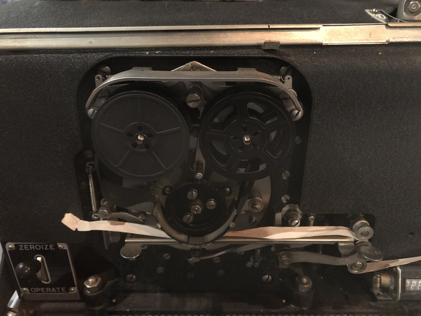
The zeroizer is an up-and-down switch at the front left, marked Zeroize and Operate (par. 207). At Zeroize, with the controller at R, holding RPT and BLANK makes every code wheel step until its cam-lobe stops it with O at the reference line. All the operating procedures in Volume 5 start from this zeroize position. The 1944 patent explains how the switch does it: at Operate it connects the index wheels to the stepping magnets; at Zeroize it disconnects them and instead connects the stepping magnets of all ten code wheels to the zeroizing contacts, so that each wheel keeps stepping until its own cam opens its own circuit (US 6,175,625, cols. 3-4; Library copy).
3.11 One Turn of the Shaft
The machine does nothing until a key is pressed. Then everything happens in one turn of the main shaft, and CSP 1100(C) par. 210(d) describes the sequence in detail:
- The key closes a circuit through a printer magnet, the printing timing contact (closed at rest) and the clutch magnet. The printer magnet is therefore energized, and the stop pin selected, before the shaft starts to turn. This is the moment the current runs through the Alphabet Maze.
- The clutch magnet trips the clutch, and the motor starts the shaft.
- About one-twentieth of a turn later, the printing contact opens and the stepping contact closes, sending a pulse through the Stepping and Index Mazes to whichever stepping magnets they reach, and to the stepping magnet of the centre Stepping-Maze wheel.
- By one-tenth of a turn the stepping contact has opened again, and “all electrical functions have been completed”.
- The rest of the turn is mechanical: the type wheel turns to the selected stop pin and the hammer prints; the stepping cam pushes the drive bars forward so that every pawl that has been unlatched by its magnet pushes its wheel one tooth; the pawls are relatched; the tape advances; the counter counts; and the clutch disengages.
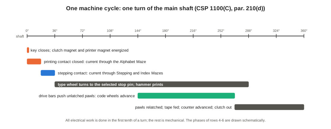
The manual draws the conclusion that matters for anyone simulating the machine: “It is important to note that the machine first enciphers the character, then advances the Code Wheels to their next position, and finally prints the character as one of the last operations of the cycle. The Code Wheels are at rest while the circuit through them is energized; no current is broken at the Code Wheel contacts” (par. 210(e)). Two consequences follow. The first letter of a message is enciphered by the wheels exactly as aligned, and every later letter by the positions left by the letter before. And because the wheels never move under current, the contacts never arc, which mattered: the manual notes that the coils of the machine generate a reaction voltage of about 750 volts when switched, enough to burn wheels and pit contacts if the spark suppressors fail (par. 214).
The stepping pawls deserve a word, because the replica of Volume 10 copies them. There are five drive bars, each lying under one wheel of the Alphabet Maze and the Stepping-Maze wheel in line with it (US 6,175,625, col. 4; Library copy). The bars move back and forth once per cycle, driven by the main shaft. Each wheel’s pawl is normally latched out of engagement; a pulse through that wheel’s stepping magnet only unlatches it, and the drive bar then does the work. “Only a momentary pulse of current through the Stepping Magnet is necessary” (par. 204(a)). The magnets choose; the motor pushes.
3.12 Power, Hand Drive and Counter
The machine ran on 105-125 volts, AC or DC, or on 24 volts DC, depending on the motor fitted; the plugs that connected the motor also switched in the right current-limiting resistors (par. 209). All the magnets and contacts of the cipher work at a low voltage, and the manual gives a startling demonstration: for emergency use there is a hand lever that turns the main shaft through a ratchet, and with it “power for operation at the Printer and Stepping Magnets may be supplied from any source capable of producing 24 volts D.C. … Tests have shown that 18 flashlight cells in series will actuate the machine 200,000 times without exhausting the battery” (par. 211(d)). The machine works on 20 to 28 volts; below 18 it fails and above 30 it is in danger.
A mechanical counter reading 0000 to 9999 counts every cycle and must be reset by hand (par. 213). Operators used it to count the letters of a message, to fill the last five-letter group with X’s, and, in the 26-30 letter check of Volume 5, to count 25 blank cycles from the zeroize position.
3.13 What the Alphabet Maze Alone Would Be
Strip away the other two rows and the Alphabet Maze is a five-wheel rotor machine of the kind Edward Hebern built in the 1920s. If its wheels stepped like an odometer, as Hebern’s did, it would be breakable by methods that were well known by 1930 — and Friedman had broken Hebern’s machines for the Navy (Volume 2). If its wheels did not step at all, it would be a single simple substitution, breakable by anyone with a frequency table.
The manual was written with that second danger in capitals: “IF, FOR ANY REASON, THE STEPPING CIRCUITS FAIL, THE CODE WHEELS OF THE ALPHABET MAZE WILL NOT STEP, AND A SIMPLE SUBSTITUTION CIPHER WILL RESULT. AN INDEX WHEEL NOT ACCURATELY POSITIONED WILL PRODUCE THIS RESULT” (par. 203(e)(1)). An index wheel left half-way between two positions breaks every stepping circuit at once. Volume 5 describes the check that caught it, and Volume 12 shows what it does to a message.
Everything that made the SIGABA strong is in how the five wheels of the Alphabet Maze move: one to four of them on every letter, chosen by a second machine that runs alongside the first. That second machine is the subject of the next volume.
Sources
- US Navy, ECM Operating Instructions, CSP 1100(C), 16 May 1944, Parts I-III and V, transcribed by Richard Pekelney: maritime.org/doc/crypto/ecm.
- Richard Pekelney, “Electronic Cipher Machine (ECM) Mark II”, USS Pampanito / Maritime Park Association: maritime.org/tech/ecm2.htm; and the source of his ECMApp emulation, maritime.org/tech/ecmapp.txt (1996-99).
- L. F. Safford and D. W. Seiler, “Control Circuits for Electric Coding Machines”, US Patent 6,175,625 B1 (Library copy), filed 15 December 1944, granted 16 January 2001: patents.google.com/patent/US6175625B1.
- Timothy J. Mucklow, The SIGABA/ECM II Cipher Machine: “A Beautiful Idea” (Library copy), NSA Center for Cryptologic History, 2015.
- George Lasry, “A Practical Meet-in-the-Middle Attack on SIGABA”, Proceedings of HistoCrypt 2019, pp. 41-49: ep.liu.se/ecp/158/005 (Library copy).
Next — Volume 4: How It Works II — The Control and Index Banks. Four live wires out of twenty-six, a meter that turns over every 26 letters, nine bundles of wire that weigh the odds, five ten-contact wheels that never move, and one letter traced through all fifteen wheels to show exactly which cipher wheels step and why.
Comments (0)