SIGABA · Volume 10
SIGABA — Volume 10 — Building a SIGABA I — Design
What a working replica has to do, the simulators that already exist, why this design sends real current through real wheels, and the wheels, contact plates, stepping units, keyboard, printer, controller and case that make it, with a full bill of materials
10.1 About This Volume
There is no SIGABA kit. The machines that survive are in museums, and none has been offered for sale; the Pampanito machine, the last in working order, went back to the Navy in 2004 (Volume 9). Anyone who wants one has to build it. This volume designs a replica; Volume 11 wires it, programs its controller and tests it against the unit’s simulator; Volume 12 runs it.
The design goal is a machine that works the way the SIGABA worked, not just one that gives the same answers. That rules out the easy route of a microcontroller pretending to be fifteen wheels. In this replica the letter goes through five real wheels as a current; the stepping decision is made by four real currents through ten more wheels and the fixed wiring between them; and the microcontroller only does the jobs that the original’s main shaft, cams and printer did: timing, pulsing the stepping magnets and printing the tape. The wheels can be lifted out, reordered and turned round, set by hand, zeroized and stepped with the numeral keys, exactly as CSP 1100(C) tells an operator to.
Two things cannot be replicated, and the design says so rather than hiding it. No wartime wheel wiring has been published, so the replica’s ten code wheels are wired to Richard Pekelney’s simulated set, the one every published simulator uses (Volume 3); its five index wheels are wired like the real wheels of the Pampanito machine. And the original’s motor-driven main shaft, clutch and type-wheel printer are replaced by solenoids and a thermal printer. Everything else is a faithful copy of function, and in the dimensions where it matters, of form.
10.2 What the Replica Has to Do
Taken from CSP 1100(C) and the simulator, the requirements are:
- Fifteen wheels in a removable unit: ten interchangeable 26-contact code wheels and five 10-contact index wheels, in three rows of five, in a basket that lifts out of the machine.
- Reversible code wheels, which means flat contacts on both faces and spring contacts in the plates between wheels (Volume 3).
- The cipher in copper: a keyboard current enters one end of the Alphabet Maze and is detected at the other, left to right to encipher, right to left to decipher.
- The stepping decision in copper: current applied to contacts F, G, H and I of the Stepping Maze, through the nine-group wiring, the Index Maze and the pair wiring, reaching one to four of five stepping-magnet lines.
- Ten stepping actuators, one under every slot of the Alphabet and Stepping Mazes, so that the meter, the zeroize and the numeral-key alignment all work. The original stepped the code wheels of the Stepping Maze’s end slots only when zeroizing and aligning.
- A cam-lobe sensor on every code-wheel slot, to zeroize, and on Stepping-Maze slots 3 and 4, to drive the meter (Volume 4).
- The operator’s controls: a typewriter keyboard with the numerals 1 to 5, the dash, BLANK and RPT; a five-position controller O P R E D; a Zeroize/Operate switch; a resettable counter.
- A printer that prints cipher text in five-letter groups and plain text with word spaces, with the word-spacer rules: space enciphered as Z, Z as X, and a deciphered Z printed as a space.
- Agreement with the simulator, letter for letter and step for step, which is how Volume 11 proves the build.
10.3 What Already Exists
Software SIGABAs are plentiful, and the replica leans on them for its verification. Hardware SIGABAs, as far as a search in November 2026 could find, are not.
Table 1 — What Already Exists
| Project | Year | What it is | Notes |
|---|---|---|---|
| Richard Pekelney, ECMApp | 1996-99 | Java emulation of the Pampanito CSP-889/2900 | The reference for everything since: the stepping rule, the group and pair wiring, the index-wheel wirings, the CSP-2900 changes; source published at maritime.org/tech/ecmapp.txt |
| Geoff Sullivan, CSG SIGABA simulator | 2002 | Windows program | cryptocellar.org/simula/sigaba; used by Lasry to cross-check his own |
| Mark Stamp, MysteryTwister C3 | 2010 | Challenge generator | Lasry found incompatibilities: wheels reset to A, the meter’s medium and slow wheels, reversed-wheel mappings |
| SJSU CRYPTSIM | 2012 | Web simulators of Enigma, Typex and SIGABA | MS project, San José State University (scholarworks.sjsu.edu/etd_projects/246) |
| Julian Weyers, CrypTool 2 | 2014 | Cryptanalysis of the SIGABA, with an implementation and visual presentation in CrypTool 2 | MS thesis, Universität Duisburg-Essen, “Kryptoanalyse der SIGABA” (PDF; Library copy) |
| Martin Grap, rmsk2 | — | Linux rotor-machine framework | Simulates the SIGABA as CSP-889 and CSP-2900 (github.com/rmsk2/rmsk2) |
| George Lasry | 2019 | Java reference simulator, printed in his HistoCrypt paper | Compatible with Pekelney’s, tested against Sullivan’s; gives a 20-letter test vector |
| CyberChef SIGABA operation (hettysymes) | 2020 | Browser operation in GCHQ’s CyberChef | Three test vectors in its test suite, two with Pekelney’s wirings |
This unit’s sigaba_sim.py | 2026 | Python, no dependencies | Passes Lasry’s vector, CyberChef’s three and the 10,000-step table of CSP 1100(C) par. 519 |
The closest hardware precedent is not a SIGABA at all but the Enigma replicas built with printed-circuit rotors and spring-loaded “pogo” pins, such as the Hackaday.io Enigma project whose rotors are built from a printed circuit board, pogo pins and a few printed parts (hackaday.io/project/156935). The SIGABA replica adapts that technique to a machine with three times as many wheels and wheels that turn round.
10.4 Three Ways to Build One
Table 2 — Three Ways to Build One
| A. Emulator in a period case | B. Real wheels, solenoid stepping (this design) | C. Real wheels, stepper-motor stepping | |
|---|---|---|---|
| Where the cipher happens | in software | in the wheels’ copper | in the wheels’ copper |
| Wheels | dummy or none; positions on displays | 15 removable, reversible wheels | 15 removable, reversible wheels |
| Stepping | software | 24 V solenoid, pawl and 26-tooth ratchet, like the original | small stepper per slot with gearing and an O sensor |
| Hand setting | buttons | turn the wheel; detent clicks | turn the wheel only with the motor unpowered |
| CSP-2900 mode | easy | not without a second pawl on wheels 2 and 4 | easy (reverse the motor) |
| Mechanical difficulty | low | moderate: ratchet, pawl and detent must be tuned | moderate: gearing, homing |
| Cost (rough, Nov 2026) | about $150 | about $1,500 | about $1,700 |
Option A is a weekend: the Sigaba class of sigaba_sim.py uses nothing but the core language and ports to MicroPython by dropping its command-line wrapper, and a Pico with a keyboard and a thermal printer is then a working SIGABA. It is also, in the end, a calculator. Option C is the most flexible. Option B is chosen because it is the original’s own mechanism: a magnet unlatches a pawl and the wheel moves by one ratchet tooth, a cam-lobe closes a contact at O, and a wheel turned by hand clicks from letter to letter on its detent. The pages that follow describe B, with C’s differences noted where they matter.
10.5 Architecture
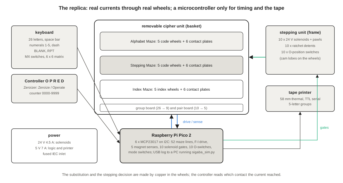
A keystroke at E goes like this. The controller (the Pico, not the switch) pulls the keyboard letter’s line low at the left-hand end of the Alphabet Maze and reads the 26 lines at the right-hand end; exactly one will have been pulled low through the wheels, and that is the cipher letter. It then pulls the common F-I line of the Stepping Maze low and reads the five magnet lines; those that read low are the cipher wheels to step. It reads the O-switches of Stepping-Maze slots 3 and 4. It prints the letter, pulses the chosen solenoids together with the meter’s (always slot 3; slot 4 if slot 3 was at O; slot 2 if both were), waits for the wheels to settle, and advances the counter. Deciphering is the same with the Alphabet Maze driven from the right. The sequence copies one turn of the original’s main shaft (Volume 3): cipher current first, then stepping current, with the wheels moving only after both have been read.
The controller never computes a substitution and never decides a stepping. If a wheel is in the wrong slot or the wrong way round, the replica prints what that machine would print, just as the original did, and the 26-30 letter check of Volume 5 finds it.
10.6 The Code Wheels
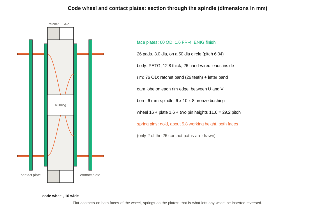
Each code wheel is a sandwich:
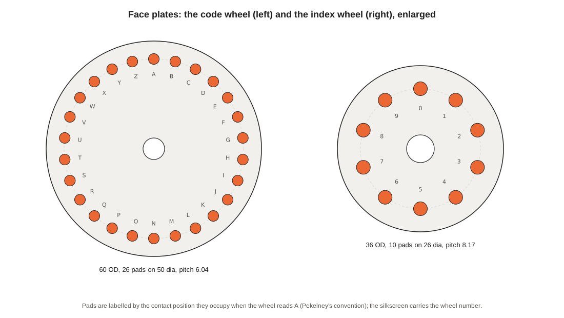
- Two face-plates, 60 mm diameter, 1.6 mm FR-4, two layers, ENIG (gold) finish. Each carries 26 round pads 3.0 mm across on a 50 mm circle, a pitch of 6.04 mm, each pad plated through to a solder pad on the inside face. The silkscreen carries the wheel number on one plate and the alphabet on the other, as the originals’ face-plates did. One design serves for all wheels; 30 plates make ten wheels, four test wheels and two spares.
- A printed body, PETG, 12.8 mm thick, with a 76 mm rim. The rim carries two bands: a 26-tooth ratchet, for the pawl and the detent, and a letter band engraved A to Z (letters printed raised and painted, or a printed paper band under clear lacquer). A cam-lobe on each edge of the rim sits between U and V, as on the originals (CSP 1100(C) par. 202), so that the wheel stops at O when zeroizing whichever way round it is fitted. The body is hollow, with an annular channel for the wiring.
- 26 wires, 30 AWG Kynar-insulated wire-wrap wire, each soldered from a pad on one plate to the pad the wiring table names on the other. The table for each wheel is generated from
sigaba_sim.py(Volume 11 gives all ten and the procedure). - A 6 × 10 × 8 mm oil-impregnated bronze bushing in the centre, running on a 6 mm stainless spindle.
The pad positions follow Pekelney’s convention: pad n is the one at contact position n when the wheel reads A. Getting this right is what makes a hand-wired wheel agree with the simulator, and Volume 11’s wheel scan checks it.
Four extra wheels, marked T, are wired straight through, A to A, B to B: Pekelney’s “straight through test rotor”, which the simulator also supports. With test wheels in four slots of a maze, the fifth wheel can be read on its own (Volume 11).
The originals’ diameter has not been found in any published source, so the replica’s 76 mm rim is a design choice, sized for a 6 mm pad pitch and a ratchet tooth big enough to print.
10.7 The Index Wheels
The five index wheels are smaller copies: 36 mm face-plates with ten pads on a 26 mm circle (pitch 8.17 mm), a 44 mm printed rim engraved with the wheel’s own ten numbers (10 to 19, 20 to 29 and so on) and ten detent notches, and a 10 mm body with ten wires inside. They have no ratchet; like the originals, they are set by hand and never stepped. Their wiring is the Pampanito machine’s (Volume 4).
10.8 Contact Plates and the Basket
Between every two wheels, and at each end of each maze, is a contact plate: a fixed printed circuit board carrying gold spring pins that press on the wheels’ pads. The inner plates carry pins on both faces, joined through the board; the end plates carry pins on the inner face only, and a connector on the outer. There are six plates per maze: four inner and two end.
The pins are Mill-Max 0907-0-15-20-75-14-11-0, gold-plated surface-mount spring-loaded contacts about 6.5 mm high free and 5.8 mm working (DigiKey listing, as of November 2026; the stroke should be checked against Mill-Max’s drawing before the plates are laid out). A code-maze inner plate carries 52 and an end plate 26, so each code maze takes 260; the Index Maze takes 100 (inner 20, end 10). With spares, about 680 pins. Wheel pitch is set by the plates: wheel 16 mm, plus two pin heights at working compression, plus 1.6 mm of board, gives a 29.2 mm pitch, and 148 mm for a code maze.
The basket is two 3 mm aluminium side plates, laser cut, joined by the contact plates (which slot into them) and by tie rods, carrying three 6 mm spindles. Like the original, it lifts out by two handles once four thumb screws are undone. To change the arrangement, the operator pulls a spindle, lifts the wheels out between the plates, and drops them back in another order or the other way round; the pin heads are rounded, and the wheels’ faces have a small chamfer so that they slide in over them. Overall the basket is about 210 mm wide and 235 mm deep.
The basket also carries the two fixed wiring boards that the original built into the frame: the group board, which gathers the 26 left-hand contacts of the Stepping Maze into nine groups for the Index Maze, and the pair board, which joins the Index Maze’s ten outputs in pairs to five magnet lines (Volume 4; the boards are drawn in Volume 11). The basket connects to the machine by two 34-way IDC ribbon connectors for the 52 Alphabet-Maze lines and one 10-way for F-I and the magnet lines. This is a simplification: on the original, the grouped end contacts were part of the machine’s frame and the basket dropped onto them (par. 203(g)).
10.9 Stepping Units
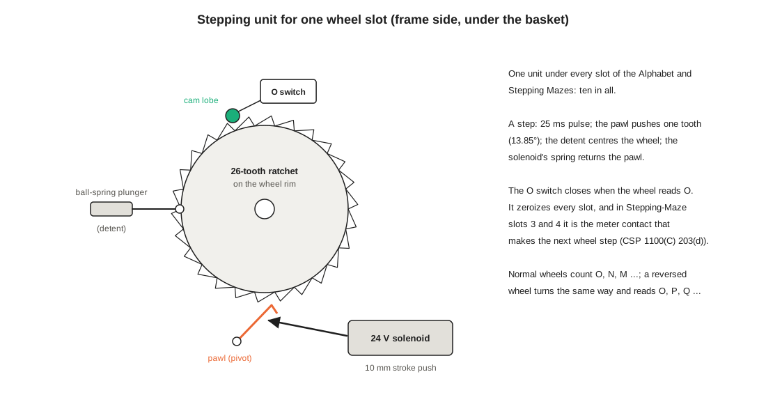
Under each of the ten code-wheel slots, fixed to the machine’s frame rather than the basket, is a stepping unit:
- A solenoid: JF-0530B, 24 V DC, push type, 10 mm stroke, about 5 N, 300 mA, with its own return spring. A 25 ms pulse is enough for one step. The original’s stepping magnets only unlatched a pawl that the main shaft then drove; in the replica the solenoid does both.
- A pawl, printed in PETG or cut from 1.5 mm brass, on a 3 mm shoulder-screw pivot, with a light torsion spring to keep its tip on the ratchet. It pushes one tooth, 13.85 degrees of wheel rotation, per stroke; a stop limits its travel so that it cannot push two.
- A detent: an M6 ball spring plunger bearing on the ratchet teeth, which centres the wheel on each letter and gives the click when a wheel is turned by hand. The original used detent rollers in the same way (par. 202(a)).
- An O-switch: an Omron D2F-01L3 subminiature switch with a roller lever, placed so that the wheel’s cam-lobe closes it when the wheel reads O.
Every code wheel steps the same way when its solenoid fires. A normal wheel’s reading goes O, N, M; a reversed wheel’s goes O, P, Q (Volume 3). Nothing in the stepping unit needs to know which way round the wheel is.
The O-switches do three jobs. When zeroizing, the controller pulses every slot whose switch is open until all ten are closed, at most 25 pulses. During operation, the switches of Stepping-Maze slots 3 and 4 are the meter contacts. And during bring-up and running, a quick check that all five Alphabet-Maze switches are not closed after a Navy alignment reproduces the manual’s test that the stepping circuits are alive (par. 309(c)(4)).
Option C replaces the solenoid, pawl and detent with a NEMA 14 stepper and a 15-tooth pinion engaging a 78-tooth gear moulded into the rim: 200 full steps × 78/15 = 1,040 steps per revolution, exactly 40 per letter. It needs a driver per slot and homes on the same O-switch.
10.10 Keyboard, Controller, Zeroizer and Counter
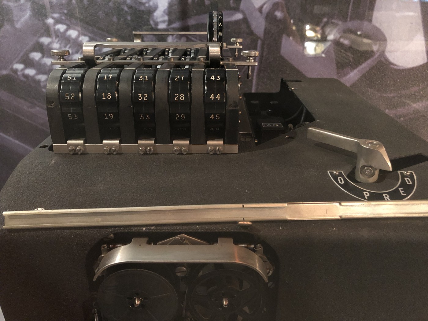
The keyboard has 36 keys: the 26 letters, a space bar, the numerals 1 to 5 (the only numerals the replica needs; 6 to 0 can be fitted as blanks for appearance), the dash, BLANK and RPT. They are MX-compatible mechanical switches with round “typewriter” keycaps, scanned as a 6 × 6 matrix with a diode per switch so that RPT can be held with any other key. The layout follows the photograph in Volume 3: QWERTY rows, with BLANK and RPT at the right-hand ends.
The controller is a one-pole rotary switch (a Lorlin CK1049 with its end stop set to five positions) under a large knob engraved O P R E D; its O position also switches the 24 V supply off. The zeroizer is a toggle switch marked Zeroize and Operate. The counter is a four-digit display (a TM1637 module) with a reset button beside it; a 24 V electromechanical impulse counter with a reset knob is the period-correct alternative.
10.11 Printer
The tape printer is a 58 mm thermal receipt printer with a TTL serial interface (Adafruit product 597 or the equivalent CSN-A2 mechanism), on its own 5 V feed. It prints in a large monospaced font, five-letter groups when enciphering and word-spaced plain text when deciphering, just as the original’s feed mechanism spaced them (par. 206(d)). Thermal paper is not gummed tape, but the printout can be cut into strips and pasted on a message form in the original manner.
10.12 Controller Electronics
A Raspberry Pi Pico 2 runs the machine in MicroPython. Six MCP23017 16-bit port expanders on its I2C bus give it the lines it needs: four for the 52 ends of the Alphabet Maze; one for the controller and zeroizer switches and the ten O-switches; and one for the ten solenoid gates, the five magnet lines and the F-I drive. Every maze line has a 4.7 kΩ pull-up to 3.3 V, so that a line is driven by pulling it low and sensed by reading it, and about 0.7 mA flows through the wheels’ contacts while a line is read: low enough to be harmless, high enough to keep gold contacts reliable. Each solenoid is switched by an IRLB8721 logic-level MOSFET with a 1N4007 flyback diode across the coil. Volume 11 gives the schematic, the pin allocation and the program.
10.13 Power and Safety
The replica runs on two supplies: a Mean Well LRS-100-24 (24 V, 4.5 A) for the solenoids and a Mean Well LRS-35-5 (5 V, 7 A) for the Pico, the expanders, the keyboard and the printer, from a fused, switched IEC inlet. Twenty-four volts was one of the original’s own supplies (Volume 3), and nothing on the replica runs above it outside the power supplies’ enclosures.
Three hazards need care:
- Inductive kick. A solenoid switched off without a diode produces a spike of hundreds of volts; the original’s spark suppressors existed for the same reason (par. 214). Every coil has its diode at the coil.
- Simultaneous pulses. Zeroizing can fire all ten solenoids at once, 3 A at 24 V; the supply is sized for it, and a 2,200 µF capacitor on the 24 V rail at the driver board covers the peak.
- Pinch points. The pawls and ratchets move fast. The stepping units sit under the basket deck, and the basket’s sides close off the wheels from the operator’s fingers while the machine is running; hand setting is done with the controller at O.
10.14 Layout
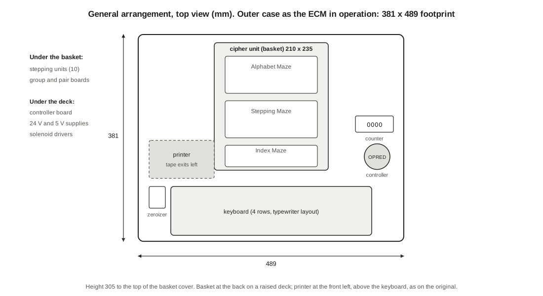
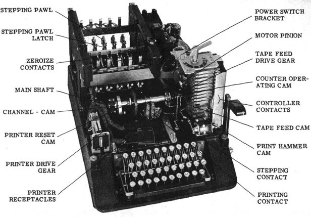
The case copies the ECM’s footprint in operation, 15 by 19¼ inches (381 × 489 mm), and stands about 305 mm high to the top of the basket cover (Pekelney). It can be built as a plywood box with a steel top plate, finished in black wrinkle paint like the original. The basket sits at the back on a raised deck, with the ten stepping units on the deck’s underside and the group and pair boards in the basket. The printer sits at the front left, above the keyboard; the controller dial, counter and fuse holders are on the right, and the zeroizer at the left, as in the manual’s own labelled photograph (Volume 3). The supplies and the controller board sit under the deck at the back.
10.15 What It Will Cost
At catalogue prices in November 2026, very roughly: spring pins about $600, printed circuit boards (eight designs, small quantities, gold finish) about $250, solenoids and switches about $120, electronics about $90, printer and paper $70, supplies and power entry $70, keyboard $70, aluminium, rods, bushings, plungers and filament about $120, and the case $100: about $1,500 in all, of which the spring pins are the largest single item. Cheaper generic pogo pins would cut that by $500, untested.
10.16 Bill of Materials
Quantities are for one machine with ten code wheels, four test wheels and five index wheels. Part numbers are examples that meet the specification; stock was not checked for every line.
Table 3 — Bill of Materials
| Item | Part | Qty | Notes |
|---|---|---|---|
| Code-wheel face-plates | PCB, 60 mm, 1.6 mm FR-4, 2 layers, ENIG; 26 × 3.0 mm pads on a 50 mm circle | 30 | 10 wheels + 4 test wheels + 2 spare |
| Index-wheel face-plates | PCB, 36 mm, ENIG; 10 pads on a 26 mm circle | 10 | 5 wheels |
| Contact plates, code mazes | PCB, 2 designs: inner (pins both faces), end (pins one face, connector) | 8 inner + 4 end | two mazes |
| Contact plates, Index Maze | PCB, 2 designs: inner and end | 4 inner + 2 end | |
| Group and pair boards | PCB, 26 → 9 groups and 10 → 5 pairs | 1 each | fixed wiring, CSP-889 |
| Spring pins | Mill-Max 0907-0-15-20-75-14-11-0, SMT, gold | 680 | 620 needed |
| Wheel bodies and rims | PETG filament | 2 kg | 14 code wheels, 5 index wheels, pawls |
| Wheel wiring | 30 AWG Kynar wire-wrap wire | 1 roll (30 m) | 26 wires per code wheel, 10 per index wheel |
| Bushings | oil-impregnated bronze, 6 × 10 × 8 mm | 20 | |
| Spindles | 6 mm stainless steel rod | 3 × 250 mm | |
| Detents | M6 ball spring plunger | 15 | 10 code slots + 5 index slots |
| Basket sides | 3 mm aluminium, laser cut | 2 | with tie rods and thumb screws |
| Stepping solenoids | JF-0530B, 24 V DC push, 10 mm stroke | 10 + 1 spare | one per code-wheel slot |
| O-switches | Omron D2F-01L3, roller lever | 10 + 1 spare | cam-lobe sensors |
| Pawl pivots | M3 shoulder screw, torsion spring | 10 | pawls printed or 1.5 mm brass |
| Controller | Raspberry Pi Pico 2 | 1 | MicroPython |
| Port expanders | MCP23017-E/SP | 6 | I2C 0x20-0x25 |
| Pull-ups | 4.7 kΩ × 8 bussed SIP network | 8 | 57 lines |
| Solenoid drivers | IRLB8721PBF MOSFET, 1N4007, 100 Ω, 10 kΩ | 10 each | |
| Keyboard | MX-compatible switch, round typewriter keycap, 1N4148 | 36 each | 6 × 6 matrix |
| Controller switch | Lorlin CK1049 rotary, 1 pole, stop at 5; knob | 1 | O P R E D |
| Zeroizer | SPDT toggle | 1 | Zeroize / Operate |
| Counter | TM1637 4-digit display module; momentary button | 1; 1 | or a 24 V impulse counter |
| Printer | 58 mm TTL thermal printer (Adafruit 597); thermal paper rolls | 1; 5 | |
| Power | Mean Well LRS-100-24; LRS-35-5; fused switched IEC inlet | 1 each | |
| Capacitors | 2,200 µF 35 V; 470 µF 10 V; 100 nF | 1; 1; 8 | |
| Small parts | 1N5819 Schottky (VSYS); 4.7 kΩ I2C pull-ups; red LED + 330 Ω; 5 A T fuse and panel holder for the 24 V rail | 1; 2; 1; 1 | |
| Connectors | 34-way IDC; 10-way IDC; 2-way and 3-way KK 254 for slots | 2; 1; 20 | |
| Controller board | PCB or stripboard, 100 × 160 mm | 1 | |
| Case | 12 mm plywood, 1.5 mm steel top plate, black wrinkle paint | 1 | 381 × 489 × 305 mm |
A printable version with tick boxes, part numbers, alternates and reference designators from the Volume 11 schematic is at the end of this volume (Printable Bill of Materials).
10.17 Printable Bill of Materials
The parts list above is also a printable PDF for the bench: SIGABA replica BOM (PDF). Each part has a row with tick boxes for ordered, in hand and fitted, the quantity and its reference designators on the Volume 11 schematic, an example part number, alternates, where to buy it, its tag and space for notes. The last page is an order log.
Next — Volume 11: Building a SIGABA II — Wiring, Controller and Verification. Ten wiring tables and 310 hand-soldered wires, the group and pair boards, the schematic and pin map, the controller’s program in one machine cycle, and a bring-up in nine stages that ends with the replica reproducing the Navy’s own 10,000-step stepping check and every letter the simulator prints.
Comments (0)