Number Sieves · Volume 8
Number Sieves — Volume 8 — Electronic Sieves, 1965–2001, and a Tiny Sieve in ATtinys
Surplus Navy delay lines, a shift-register machine scrapped by mistake, three generations of Manitoba sieves ending in a custom chip, the algorithm that made them unnecessary — and a 2026 sieve of thirty eight-pin microcontrollers
8.1 About This Volume
Volumes 6 and 7 described the two mechanical sieves of D. H. Lehmer: fifty candidates a second on bicycle chains, five thousand on photoelectric gears. This volume follows the idea into electronics. It begins with the software sieves Lehmer wrote for the first electronic computers, then turns to the special-purpose hardware that outran them: Lehmer’s Delay Line Sieve of 1965, built cheaply from surplus Navy delay lines and run around the clock for a decade; his shift-register sieve, never finished; and the University of Manitoba’s three machines — UMSU, OASiS and the MSSU — which by 1993 combined thirty-two custom chips into a sieve rated at more than six billion candidates a second. It explains why the hardware lasted so long and what ended it, which was not a faster machine but a better algorithm, published by Daniel J. Bernstein from a computation of December 2001.
The second half describes a machine built in 2026: kbsriram’s A Tiny Sieve, thirty ATtiny412 microcontrollers on a stripboard backplane, clocked and supervised by a Raspberry Pi Pico, which follows the architecture of Lehmer’s last sieve design and re-runs his published problems at the original machines’ speeds. This volume summarises its design and results; Volume 13 is the build procedure.
8.2 Sieves in Software, 1946–1970
The first electronic sieve was a program. In July 1946, over a holiday weekend at the Moore School, the Lehmer family — Dick, Emma and their two children — reconfigured the ENIAC as a sieve, on John Mauchly’s suggestion that “we ought to use some of the arithmetic units to make a kind of sieve” (Huskey, “Derrick Henry Lehmer,” IEEE Computer Pioneers; Volume 5). In the 1950s Lehmer wrote a seventeen-ring sieve for the SWAC at the National Bureau of Standards’ Institute for Numerical Analysis that examined about 1,450 candidates a second, and set out the general problem in “The sieve problem for all-purpose computers” (Math. Comp. 7 (1953) 6–14). In the 1960s John Brillhart’s IBM 7094 program reached 100,000 to 150,000 a second with 21 or 22 congruences; Lehmer explained the trick as combining “many moduli into five or six very long chains which filled most of memory,” so that one machine word tested many rings at once (R. F. Lukes, A Very Fast Electronic Number Sieve, PhD thesis, University of Manitoba, 1995, p. 17; Huskey). An early-1970s program on the 64-processor ILLIAC IV reached 15 million a second (Lukes).
Software made sieving flexible — any modulus, any number of rings — but a general-purpose computer pays for every step with instruction fetches and memory traffic. A ring of bits does not need a computer; it needs a loop of storage that shifts once per step, and an AND gate. That observation drove forty years of special-purpose hardware.
8.3 Electronic Proposals That Were Not Built
Lehmer drafted the first electronic sieve on his return from the ENIAC, in an unpublished 1946 proposal for an “Electronic Sieve” of vacuum tubes, reconfigurable by plugging and unplugging identical logic modules, at an estimated 100,000 to 200,000 candidates a second. The same document floated an “Acoustic Sieve” in which, in Lukes’s words, “the periodic element would be a tube of ethylene glycol with a piezo-electric crystal at each end.” Neither was funded (Lukes 1995, pp. 16–17). Later, Lehmer and Paul Morton of Berkeley’s electrical engineering department tried a sieve of electronic counters and abandoned it after about two years for reliability problems (Huskey).
The most ambitious unbuilt design came from D. G. Cantor, G. Estrin, A. S. Fraenkel and R. Turn: “A very high-speed digital number sieve,” Math. Comp. 16 (1962). Their shift-register rings, clocked at 5 MHz, would have exceeded 10¹⁰ candidates a minute, and the paper introduced two ideas that every later sieve used: several solution taps per ring (“observation posts”), so that one clock tick tests several candidates, and the coupling of the sieve to a general-purpose computer in a “fixed plus variable” system, the computer supplying any rings the hardware lacked (Lukes 1995, pp. 18–19). It was not built; Lukes judged that “it would be another 20 years before a machine of similar capabilities was to be built.”
8.4 The Delay Line Sieve, DLS-127 (1965)
8.4.1 What it was
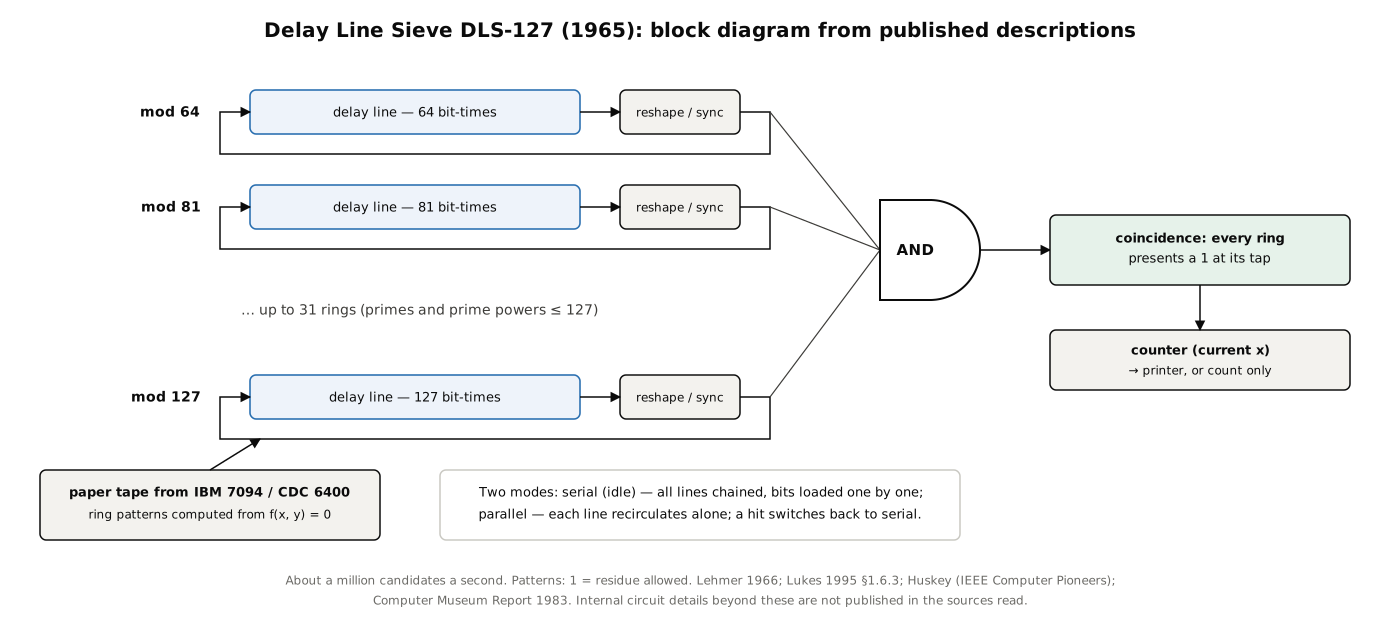
Lehmer and Morton’s working answer was the Delay Line Sieve. In a delay line an electrical pulse entering one end emerges at the other a fixed time later, so a line whose delay equals m clock periods, fed back on itself through a pulse-reshaping circuit, holds a ring of m bits that circulates for ever — a bicycle chain made of time. Load each ring with 1s at its acceptable residues and 0s elsewhere, and the moment every ring presents a 1 at its output together is a solution (Lukes 1995, p. 17).
Lehmer announced it in Mathematics of Computation in 1966:
“This machine is now operational and a substantial percentage of its free time is now available to number theorists and combinatorial analysts everywhere. The DLS-127 combines up to 31 sets of arithmetical progressions, whose differences are primes or powers of primes less than or equal to 127, at the rate of a little over a million cases per second.” (D. H. Lehmer, “An announcement concerning the Delay Line SIEVE DLS-127,” Math. Comp. 20 (1966), Notes, pp. 645–646)
Thirty-one rings is one for each prime up to 127. An automatic set-up procedure accepted any Diophantine equation f(x, y) = 0 with integer coefficients “of arbitrary size”: “Should the user have a problem which can be put into the form f(x, y) = 0 he needs to submit only the coefficients of f.” The announcement’s list of six problem types runs from representations by quadratic forms to the binomial units of algebraic number fields.
8.4.2 How it was built and run
The record is fragmentary but consistent:
- The delay lines were Navy surplus, and electrical rather than acoustic: Huskey says Lehmer was “leery” of mercury delay lines. The Computer Museum’s 1983 report: “Navy surplus delay lines store the acceptable remainders for each modulus and circulate them synchronously” (R. Rubinstein, “D. H. Lehmer’s Number Sieves,” The Computer Museum Report, Spring 1983, p. 4). It “also had vacuum-tube components” (Wikipedia, “Lehmer sieve”).
- Two modes. “In the idle mode all lines were connected in series, and bits were inserted one at a time using counting circuits; then the system was switched to parallel where each delay line recirculated independently. When a coincidence occurred the system automatically switched back to serial” (Huskey).
- Input came on punched paper tape prepared by a program on an IBM 7094 (Lukes) or a CDC 6400 (Wikipedia; kbsriram, from Lehmer’s 1982 lecture). kbsriram reports from that lecture that a typical problem’s ring patterns were punched onto “a 25 foot paper tape of 2,877 characters” read by a photoelectric tape reader, and that survivors were printed on a Clary printer (kbsriram, build log 6); the lecture itself was not reviewed for this series. After printing a solution, the sieve could load the next problem from its tape automatically (Lukes).
- A counting mode reported how many solutions fell in a range without printing them — decisive for the pseudosquare problem below.
- Cost and economy. It was built “as an unsponsored educational project of the Departments of Mathematics and Electrical Engineering” at Berkeley (Rubinstein 1983, p. 4); Wikipedia gives the cost as about $2,000 including about $150 for the delay lines, a figure not traced to a primary source here. Lehmer’s own sales pitch, quoted on the report’s cover: “In competition with the IBM 7094 [it] makes a good showing, especially on economic grounds. It is roughly 10 times faster than the 7094, and costs about 2 cents an hour to operate.”
- Reliability. Lehmer in 1980: “That’s the way the delay line sieve has been operating for ten years now, 24 hours per day. We have no maintenance and since the whole system is just a long piece of wire, nothing ever went wrong to speak of except for occasional counter printer trouble” (quoted by Huskey).
- DLS-157. In the early 1970s six more rings, built from shift registers rather than delay lines, extended it to the primes up to 157 (Lukes 1995, pp. 17–18).
Sources differ on the start date — 1965 (Lukes) or 1966 (the Computer Museum report; Williams and Shallit) — and the 1966 announcement says only that it was “now operational.” Its most-cited factoring feat is a 33-digit divisor of 2¹³⁶ + 1, which took 2,600 hours (H. C. Williams & J. O. Shallit, “Factoring integers before computers,” 1994, p. 514) — evidence both of its endurance and of how much the problem had outgrown it. Williams and Shallit note that “up to 1970 these sieve methods were still the fastest techniques known for factoring.”
8.4.3 Pseudosquares on the delay line
The DLS-127’s best-known results are in D. H. Lehmer, Emma Lehmer and Daniel Shanks, “Integer sequences having prescribed quadratic character” (Math. Comp. 24 (1970) 433–451), which solves six problems of one family: find the least N with a prescribed pattern of quadratic residues and non-residues modulo the odd primes up to p. Problem I is the pseudosquare — the least non-square N ≡ 1 (mod 8) that is a quadratic residue of every odd prime up to p — which Kraitchik had carried by hand to p = 47 and the chain sieve to 61 (Volume 6). “Using the DLS 127 this table was recently extended to p = 127.”
The difficulty is the one Lehmer met in 1928: every odd perfect square satisfies every congruence, so the true answer is buried among squares. The paper gives a sense of scale: for the primes up to 83 there are 168,091 solutions below 1,308,943², of which 161,409 are squares and only 6,682 are pseudosquare solutions. The delay-line sieve printed survivors on paper and could not test them as they came. Instead the Lehmers used the counting mode: “the number of unwanted perfect squares ≤ X is exactly the number … of numbers prime to Pₘ … and ≤ X^½. This, in turn, is the number of solutions … given by the Sieve of the trivial Diophantine equation xy = 1. These two problems were run alternately, using a logarithmic search procedure until the extra nonsquare solution was located and verified.” The answer for p = 127 is 196,265,095,009 (Table I of the paper). The paper ends: “The DLS 127 is available to anyone with a suitable problem without charge.”
8.5 The Shift-Register Sieve, SRS-181
Lehmer’s next machine replaced delay lines with integrated-circuit shift registers. The SRS-181 was to have forty-two rings, one for each prime up to 181, built from off-the-shelf 8-bit shift-register chips, with a single solution tap and a shift rate of 16 million a second; it was designed as a stand-alone machine with “a complex array of displays and switches,” and could search or count. Morrison and Brillhart expected it to be operational by the end of 1974. It was not completed: “this uncompleted machine was mistakenly scrapped when Lehmer was away from Berkeley” (Lukes 1995, pp. 19–20). Williams and Shallit list it at 20 million a second (1975, 42 rings). M. R. Williams’s short account says “in the 1970s he constructed one from integrated circuit shift registers that could work at 20 million per second” (M. R. Williams, “Lehmer Sieves”); whether it ever ran, even in part, is unclear.
8.6 The Manitoba Sieves
Lehmer’s successors in sieve-building were at the University of Manitoba in Winnipeg, under H. C. Williams, who supervised three generations of machines and the theses that document them.
8.6.1 UMSU (1982–83)
The University of Manitoba Sieve Unit, built by Cameron Patterson and Williams, began as a plan to rebuild the SRS-181 and grew into the first realisation of Cantor’s “fixed plus variable” idea: a sieve attached to a minicomputer host — a DEC PDP-11/03 at first, later a PDP-11/45 — as a peripheral (Lukes 1995, pp. 20–21; C. D. Patterson, Design and use of an electronic sieve, thesis, University of Manitoba, 1983, MSpace). More than 500 TTL integrated circuits on three wire-wrapped boards implemented shift-register rings for the first 32 primes, the first four as the prime powers 64, 81, 25 and 49. A 16.67 MHz shift clock with eight solution taps per ring gave 133 million candidates a second.
UMSU introduced most of the operating practice later sieves kept: virtual rings emulated by the host for moduli the hardware lacked, on-line filtering of survivors by the host, automatic restart after a power failure, a plain-text problem-file format, a problem queue — and checkpointing. “Testing for the presence of a hardware error was performed by predicting the contents of the shift-register rings based on the initial contents of the rings and the counter value and comparing this to the actual ring contents. In the event of a hardware error or power-failure, the sieve problem could be restarted using the state information of the last successful checkpoint” (Lukes 1995, p. 21). The 2026 Tiny Sieve below does exactly this.
8.6.2 OASiS (1988–89)
All the previous sieves had fixed moduli. A. J. Stephens and Williams’s Open Architecture Sieve System (OASiS) used sixteen 8K RAM chips as sixteen rings of any length up to 8,192, so a user could combine moduli — 5 × 7 × 11 × 13 = 5,005 in one ring, for example — and fit up to 37 moduli, all the primes to 157, into sixteen rings. A 13.3 MHz shift rate with sixteen solution taps gave 215 million a second (Lukes 1995, p. 21; A. J. Stephens, OASiS: An Open Architecture Sieve System for Problems in Number Theory, PhD thesis, University of Manitoba, 1989, MSpace). Its weakness was its link to the host, a MicroVAX II on a 9,600-baud serial line: loading or checkpointing could take ten minutes, and on problems with many survivors filtering on the host became the bottleneck. A second OASiS was built in 1991 from spare boards, and with UMSU these machines pushed the table of known pseudosquares to L₂₂₃ and beyond (Lukes 1995, p. 25; R. F. Lukes, C. D. Patterson & H. C. Williams, “Some results on pseudosquares,” Math. Comp. 65 (1996) 361–372).
Meanwhile, at the Supercomputing Research Center in Maryland, N. D. Bronson and D. A. Buell implemented a sieve on SPLASH, a reconfigurable array of 32 field-programmable gate arrays: 22 rings for primes and prime powers from 3 to 127, 64 solution taps at 16 million shifts a second — 1.024 billion candidates a second, the fastest single sieve when Lukes wrote (Lukes 1995, pp. 22–23).
8.6.3 The Scalable Sieve Unit and the MSSU (1991–93)
The last and fastest Manitoba machine put a whole sieve on a chip. Cameron Patterson, by then at the University of Calgary, designed the Scalable Sieve Unit (SSU): rings for the first 30 primes (2 to 113, the first four enlarged to 16, 9, 25 and 49), a 44-bit counter, eight solution taps per ring each with its own 30-input AND, a two-stage pipeline, and a serial scan path for loading and reading the rings. It was a 10,000-gate channelled gate array in mature 2 µm CMOS, a 1 cm² die in a 48-pin ceramic DIP, made “at only a nominal cost” by the Alberta Microelectronic Centre; designed for 33 MHz, it ran at 24 MHz to limit heat, giving 24 million × 8 = 192 million candidates a second per chip (Lukes 1995, pp. 26–29; Lukes, Patterson & Williams 1996, p. 366).
Richard Lukes’s Manitoba Scalable Sieve Unit (MSSU), completed in 1993, ran up to 32 SSU chips in parallel under a Motorola 68332 controller that did the survivor filtering itself, so the host link no longer mattered. Lukes’s comparison table gives “192 (6144 aggregate)” million candidates a second; the 1996 paper says “the raw aggregate sieving rate of the MSSU is thus in excess of 6.4 billion integers per second” — although 32 × 192 million is 6.144 billion, and the 6.4 billion often quoted for the machine appears to come from that sentence (Lukes 1995, p. 33; LPW 1996, p. 366). Partitioning a problem across chips multiplies the effective rate further: splitting the pseudosquare problem into 30 residue classes modulo 9,240 (combining 8, 3, 5, 7 and 11), one per chip, gave an effective “1.774 trillion/sec.” With filtering on the controller, the pseudosquare search ran at 35.6 per cent of the theoretical rate in its first hour, when squares are dense, rising past 99 per cent at higher counts. Checkpoints ran hourly. The MSSU extended the pseudosquares from L₂₂₃ to L₂₇₁ and searched all pseudosquares and negative pseudosquares up to 10¹⁹ (LPW 1996).
8.7 Why the Hardware Lasted, and What Ended It
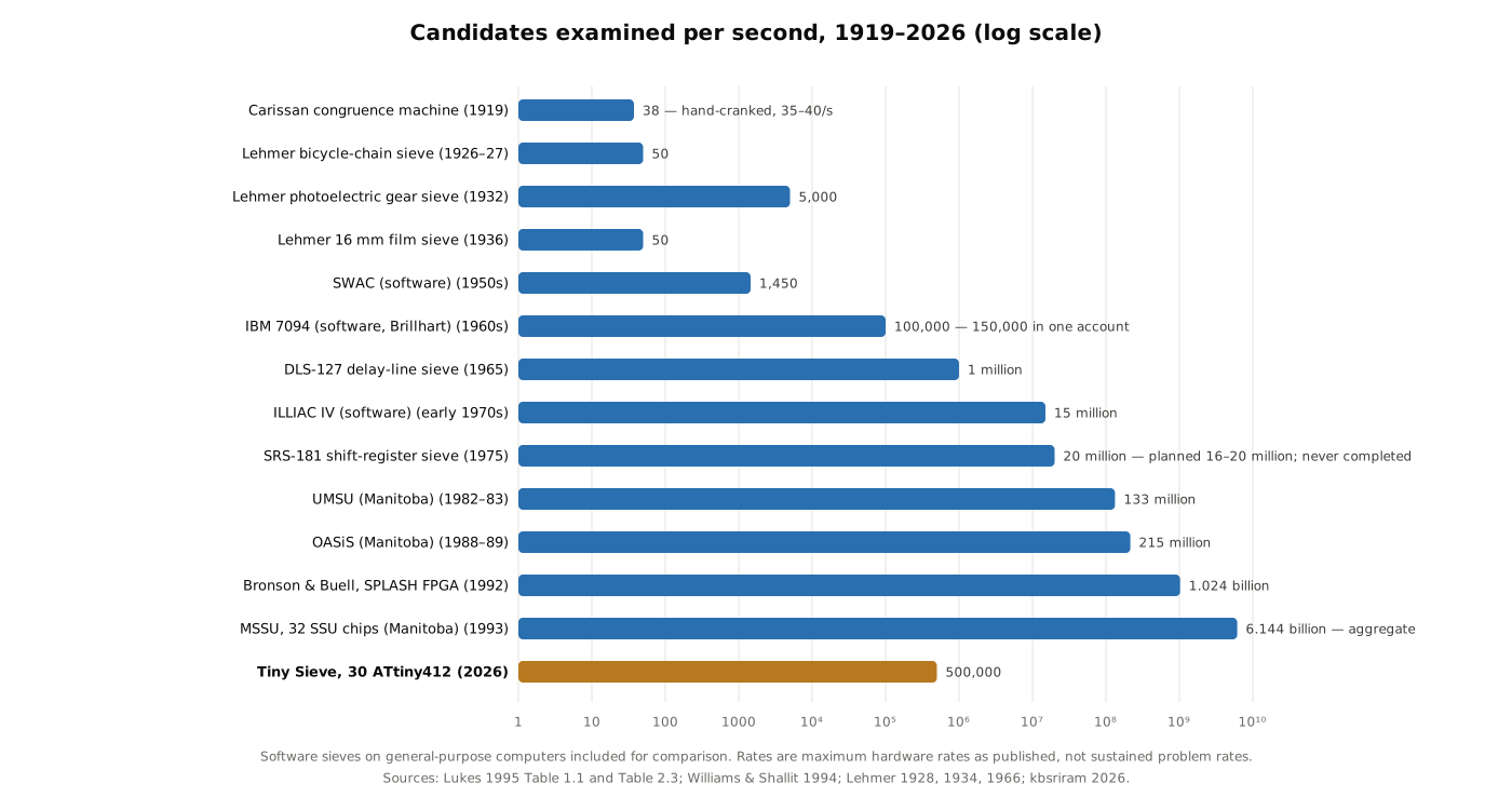
A hardware sieve does no arithmetic. Each step is a shift and an AND, so the design scales with whatever technology is cheapest — chains, gears, delay lines, TTL, gate arrays — without the instruction decoding and memory hierarchy of a general-purpose processor. kbsriram puts it in one sentence: “A sieve is fast because rejecting is cheap. It does no arithmetic, so it absorbs every hardware improvement” (kbsriram, project details). That is why a special-purpose device kept pace with, and on its own problems beat, general computers for seventy years: 50 a second in 1927, a million in 1965, billions in 1993.
The limit was algorithmic. However fast its rings, a sieve examines every integer in its range. Daniel J. Bernstein’s paper “Doubly focused enumeration of locally square polynomial values” names three ways to find the x in a range with x mod m₁ in a set S₁ and x mod m₂ in a set S₂. Unfocused enumeration tries every x, checking “the next bit in each array” — the hardware sieve’s method. Focused enumeration generates only the arithmetic progressions allowed modulo m₁ and checks each against m₂. Doubly focused enumeration splits the moduli into two large groups, generates the allowed residues for each, and finds their coincidences by sorting and matching, so that the work grows with the number of survivors rather than the size of the range (D. J. Bernstein, “Doubly focused enumeration of locally square polynomial values,” dated 2003-09-28, printed in a 2004 volume of lectures in honour of the sixtieth birthday of Hugh Cowie Williams).
The demonstration was the pseudosquare problem itself. In December 2001 Bernstein ran a doubly focused search on a single Pentium 4 at 1,406 MHz for ten days — about 1.2 × 10¹⁵ clock cycles — and showed that every non-square positive integer below 24 · 2⁶⁴ ≈ 4.4 × 10²⁰ fails to be a square modulo some prime up to 283. The chain of sieve computations “initiated by Kraitchik in 1924 and continued by Lehmer, Lehmer, Shanks, Patterson, Williams, Stephens, and Lukes,” he wrote, had established the corresponding bound only up to about 7 × 10¹⁹, “with considerably more effort.” His moduli were large — one was 41 · 43 · 47 · 53 · 59 · 61 · 71 · 73 — and a general-purpose computer could handle them because it never stepped through the integers one by one. Once the survivors could be generated directly on ordinary computers, there was no longer any reason to build a machine to step through them. kbsriram’s summary: “What ended them was a better algorithm, not faster hardware.”
Sieving did not end; it moved inside other algorithms. The quadratic sieve and number field sieve of Volume 10 sieve over a range of polynomial values with logarithms rather than bits, and Adi Shamir’s TWINKLE (1999) and Shamir and Tromer’s TWIRL (2003) proposed special-purpose optical and electronic devices for that kind of sieve. Those belong to the cryptographic story of Volume 10.
8.8 A Tiny Sieve in ATtinys (2026)
8.8.1 The idea
In September 2026 the maker kbsriram published A Tiny Sieve: Lehmer’s math machine in ATtinys on Hackaday.io, with firmware, host code, schematics and Gerber files on GitHub (project page; github.com/kbsriram/a-tiny-sieve). Its architecture comes from the design Lehmer described in his 1982 lecture: “a bank of ROM and counter pairs, one per modulus, stepped together by a shared clock,” with a general-purpose computer to load the patterns, drive the clock and check survivors. kbsriram is explicit that his board is “my implementation based on that design, and not a replica.” Each ROM-and-counter pair becomes one ATtiny412, an 8-pin microcontroller; the computer becomes a Raspberry Pi Pico’s RP2040.
The project’s explanation of a sieve is the clearest short one in print:
“Imagine a room of musicians, each following a repeating pattern of claps. One claps every third count. Another claps on counts 1, 4 and 5 of a repeating 5-count pattern. A conductor counts upward, and if any musician claps on a count, that number is thrown out. A number that passes in silence goes off for a separate, expensive check.” (kbsriram, project details)
8.8.2 Three chips and a buzzer
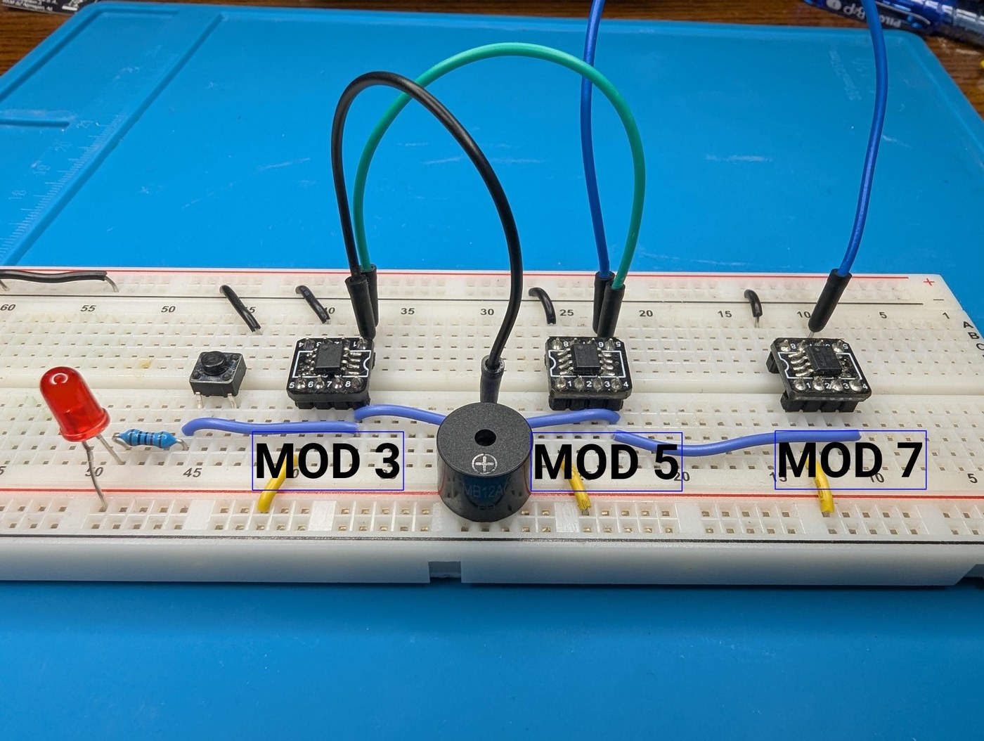
The first build log, “The sound of sieving,” solves y² − 2x² = 4001 with three ATtiny412s holding the patterns for 3, 5 and 7, a push-button as the clock, and a piezo buzzer on the shared reject line, so that each rejection is audible and survivors are silences. The first silence is at x = 17 (not a solution); at x = 38, 2 · 38² + 4001 = 6889 = 83², the first solution, reached after testing about 13 per cent of the candidates (build log 1).
8.8.3 Two shared lines
The architecture that the later builds keep is set in the second log (build log 2, “Sieving versus checking”; code/02 README):
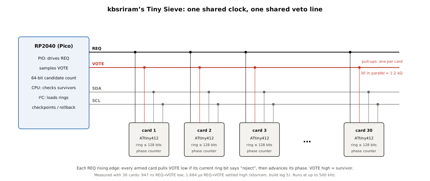
- REQ, a clock from the Pico to every chip. “Each rising edge makes every chip read one bit of its ring and advance its counter by one.” The candidate number itself “never reaches the ATtinys — they only ever advance their ring counter and read a bit.”
- VOTE, one wire shared by every chip, wired open-drain: “A chip that rejects drives it low; a chip that accepts leaves the pin as a high-impedance input. So VOTE is high only if no chip rejected.” This is the bicycle-chain machine’s all-springs-lifted test, in silicon.
- I²C, used before a run to load each chip’s modulus and ring — “its modulus p plus 16 bytes = 128 bits, one bit per residue,” which caps the modulus at 128. The ring sits in RAM, so any card can hold any modulus: this is the “adjustable sieve” Lehmer wanted in 1982.
The Pico’s PIO state machine drives REQ, samples VOTE near the end of each period and keeps a 64-bit candidate count, pushing a candidate into a FIFO only when VOTE stayed high; the main processor tests those survivors.
With only three moduli (5, 11 and 23) the breadboard version factored 5,283,065,753,709,209 — the number the gear machine factored at Burt Laboratories in 1932, using the same a² + 7(4k)² formulation — but it was badly unbalanced: the sieve scanned 5.68 million candidates in 113 seconds and passed 740,000 of them, and the Pico spent 23 minutes checking survivors at about 1.85 ms each, leaving the sieve idle 92 per cent of the time. The whole run took 1,471 seconds, about the same as the 1932 machine, despite stepping ten times faster. A sieve in that state is, in the Manitoba terminology, filter-bound. “The fix is more moduli”: twelve, kbsriram estimated, would cut the survivors from 740,000 to about 1,100.
8.8.4 Thirty cards
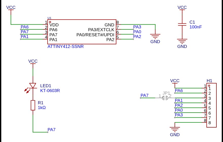
Each modulus became a small card: an ATtiny412, a 100 nF decoupling capacitor, an LED with a 1 kΩ resistor on PA7 that lights whenever that card votes to reject, an 8-pin right-angle header, and a jumper that can route PA7 to the header instead (build log 3, “A modular modulus”; hardware/modulus). Thirty assembled boards cost $81 with shipping and tariffs, “around $2.70 a modulus”; every board is identical, since the modulus is loaded at run time. A test jig checked each card for shorts, bridges and opens before it received its final firmware (build log 4, “Qualify the moduli”).
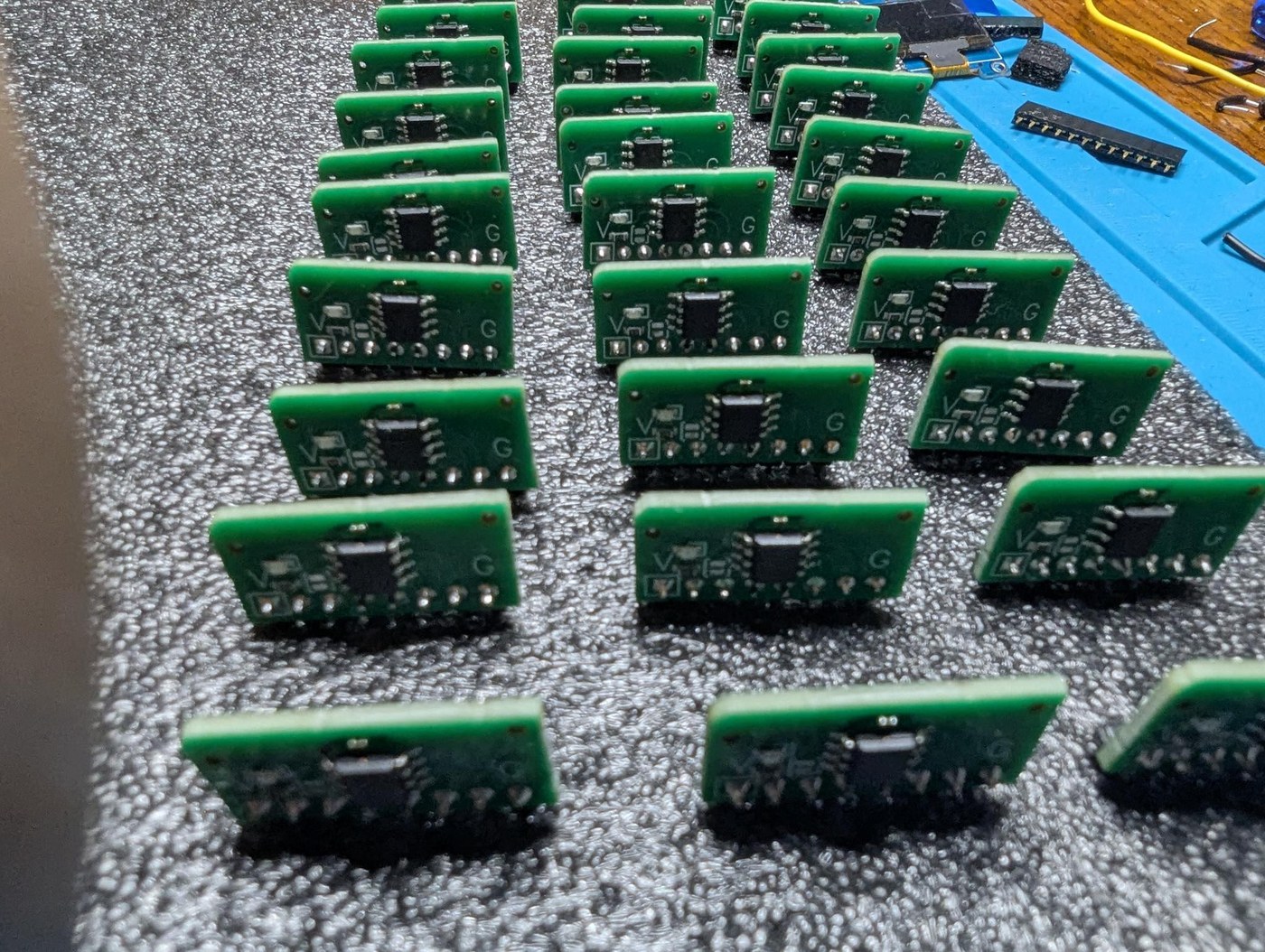
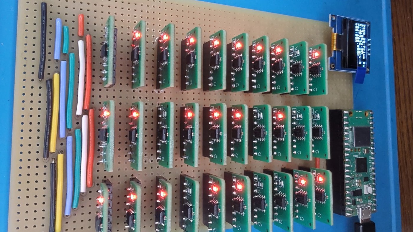
The cards stand in three rows of ten on a 3U Eurocard stripboard backplane with the Pico on the left and a small OLED display in the corner (build log 5, “The modulus chorus rehearses”; code/05 README). The whole machine draws about 131 mA from the Pico’s 3.3 V regulator.
8.8.5 Making it fast and making it trustworthy
Two problems dominate the fifth build log, and both are old ones.
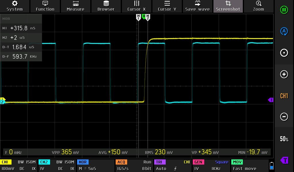
Speed is set by how quickly the VOTE line can fall and rise. The first firmware took about 5 µs to vote after a REQ edge, and the line, held up only by the Pico’s weak internal pull-up, took about 10 µs to recover, limiting the clock to 50 kHz. The final firmware moves the vote into a hand-written interrupt handler — six assembly instructions, four registers reserved across the whole build, the next phase’s port-direction byte precomputed — so that “the first instruction executed drives VOTE.” The internal pull-ups of all thirty cards, about 35 kΩ each, act in parallel as about 1.2 kΩ. With all thirty cards fitted kbsriram measured 947 ns from a REQ rising edge to VOTE low and 1.684 µs to VOTE settled high — about 600,000 candidates a second — and the production runs use 500 kHz. He also corrected an earlier error: at 3.3 V the ATtiny412 is rated for only 10 MHz, and the faster figure had come from running it out of specification at 20 MHz. “Getting into the MHz range needs a different arrangement: each card driving its own VOTE line actively, with all thirty collected in a wide AND gate. That is what the later machines did” (build log 5).
Trust is the harder problem. With one open-drain line and no error detection, “a single mistake can silently make a run worthless. A card stuck holding VOTE low rejects valid candidates, and the run then completes and claims no solutions exist” — the same failure mode as a chain-sieve contact that never closes. kbsriram’s answers:
- A CRC-8-checked I²C protocol in which every command returns a response code, and a STATUS command that reports a card’s ring position, whether it is armed, its modulus, firmware version and the reason for its last reset, so that a brown-out mid-run is visible.
- Pre-run self-tests: an I²C roll call; the scan repeated with REQ held high and then low, to catch any bridge to REQ; ten REQ edges with every card disarmed, during which VOTE must stay high; an “LED walk” lighting each card in slot order to prove that addresses match positions; and each card armed alone and checked against its own ring. When the backplane first came up, three cards did not answer; reseating them fixed it — “the female headers seem to collect lint.”
- Checkpoints and rollback during a run, in the UMSU manner: “During a run it periodically pauses and compares every counter against its expected value, checkpointing when they all agree. A card that misses a clock would silently reject at the wrong count and ruin the run, so a failed check rolls the machine back to the last checkpoint” (project details). In the final code the runner checkpoints every 15 minutes, updates the display every minute, and disarms every card the moment a solution is found (code/06 README).
8.8.6 Re-running Lehmer
The final build log runs the published problems of three Lehmer machines at each machine’s own speed: 50 candidates a second with nineteen cards for the 1928 chain sieve, 5,000 a second with thirty cards for the 1932 gear sieve, and the board’s full 500,000 a second for the six problems of the 1970 delay-line paper (build log 6; raw console output in code/06/results.md):
Table 1 — The final build log runs the published problems of three Lehmer machines at each machine's own speed: 50 candidates a second with nineteen cards for the 1928 chain sieve, 5,000 a second with thirty cards for the 1932 gear sieve, and the board's full 500,000 a second for the six problems of the 1970 delay-line paper ([build log 6](https://hackaday.io/project/206556-a-tiny-sieve-lehmers-math-machine-in-attinys/log/250911-the-modulus-chorus-plays-for-us); raw console output in [code/06/results.md](https://github.com/kbsriram/a-tiny-sieve/blob/main/code/06/results.md))
| Problem | Source | Rate | Published | Tiny Sieve | Stops |
|---|---|---|---|---|---|
| 9,999,000,099,990,001 | 1928 chain sieve | 50/s | ”about 2 hours” | 2 h 14 min 09 s | 2 |
| A factor of 3¹¹¹ + 1 | 1928 chain sieve | 50/s | ”only 4 seconds” | 2.96 s | 1 |
| 4,500,383,424,373 as a sum of two squares, case 1 | 1928 chain sieve | 50/s | one stop, not a solution | 1 h 05 min 42 s (range exhausted) | 1 |
| Same, case 2 | 1928 chain sieve | 50/s | ”stopped only once” | 52 min 37 s | 2 |
| 2⁷⁹ − 1 | 1933 gear sieve | 5,000/s | ”12 s” (per kbsriram, from the 1933 Monthly article) | 11.31 s | 1 |
| 2⁹³ + 1 | 1933 gear sieve | 5,000/s | ”a few seconds” | 1.41 s | 1 |
“Every solution matched the published one,” and his sieving rate ran about 0.5 per cent below the clock because of checkpoints and display updates. The two extra stops on the chain-sieve problems — values that pass every chain up to 67 and are first rejected by 73 — are discussed in Volume 6, where they were checked independently for this series. On 5,283,065,753,709,209 with thirty moduli, only two candidates survived, both genuine representations, and two of the thirty cards never rejected anything: “He couldn’t swap in different moduli because they were fixed by the gears he had.”
For the delay-line problems no running times were ever published, so only the answers can be compared; all six match the values for p = 127 in Lehmer, Lehmer and Shanks (1970), with running times on the Tiny Sieve from 11 minutes 21 seconds (Problem IV) to 7 hours 39 minutes (Problem II). Problem I, the pseudosquare, behaved differently from every other run: over 50,000 perfect squares survived the sieve, against a prediction of 50,450. Where Lehmer had to count survivors and binary-search the range, “my RP2040 tests each survivor as it comes out and discards the squares without pausing the sieve,” and found L₁₂₇ = 196,265,095,009 after about 4 hours 34 minutes.
kbsriram’s other historical findings — the gear machine’s period, and the two unreported chain-sieve stops — are taken up in Volumes 7 and 6, where they are set against the primary sources. In brief: both stops are confirmed by independent arithmetic; the period’s arithmetic is correct, but the tooth counts it assumes (64, 27, 25, 49) conflict with Lehmer’s 1934 description and with the labels on the surviving machine.
8.8.7 What it is, and what it is not
The Tiny Sieve is not a fast sieve by the standards of 1993; at 500,000 candidates a second it is half the speed of the 1965 delay-line machine and about one twelve-thousandth of the MSSU. Its open-drain bus is the limiting factor, and kbsriram names the remedy. What it is, is a faithful working model of the architecture every electronic sieve converged on — a fast, dumb rejecter stepped by a shared clock, and a slower, clever checker that loads it, drives it and tests what survives — built from about a hundred dollars of parts, documented completely, and checked against the historical record problem by problem. That combination of openness and verification is why this series uses it as the electronic build of Volume 13 and the test bench of Volume 14.
8.9 Hand-off to the Build
Volume 13 turns this summary into a procedure: ordering the modulus cards from the published Gerbers and bill of materials, building the test jig and the stripboard backplane, flashing thirty cards at thirty I²C addresses, running the self-tests, and reproducing the results table above. The schematics, layout files and code are all at github.com/kbsriram/a-tiny-sieve; the six build logs on Hackaday.io explain the design decisions behind them.
Next — Volume 9: What a Sieve Can Solve — Worked Problems from Easy to Hard. From a two-modulus toy to Lehmer’s 1928 factorisations and the pseudosquares: how to turn a question about whole numbers into rings of acceptable residues, how many moduli a problem needs, and when a sieve will drown in its own survivors.
Comments (0)