Number Sieves · Volume 6
Number Sieves — Volume 6 — The Bicycle-Chain Sieve (1926–1928)
Nineteen loops of chain, a shaft, a brass bar and a revolution counter: how D. H. Lehmer's first machine worked, what it solved, and the two stops its 1928 paper does not mention
6.1 About This Volume
Volume 5 ended with the strip method — congruence conditions written on paper strips and slid down a ruled table — and with the first attempts to mechanise it. This volume is about the first machine that did so reliably enough to produce new mathematics: the frame of bicycle chains that Derrick Henry Lehmer built as a Berkeley undergraduate and described in the American Mathematical Monthly in March 1928. It sets out, as exactly as the surviving record allows, what the machine was made of and how each part did its job: the nineteen chain loops and why their lengths were 64, 27, 25, 49, 22, 26 and the primes from 17 to 67; the pins that marked acceptable residues; the springs, the brass bar and the relay that stopped the motor; and the revolution counter that gave the answer. It then works through the problems the 1928 paper reports, compares the original with the 1981 reproduction at the Computer History Museum, and examines a finding made in 2026 by kbsriram, whose electronic replica of the machine stopped twice where Lehmer’s paper reports no stop.
The volume is written for two readers: one who wants to understand how a loop of chain can do number theory, and one who intends to build a working copy. For the second, every fact about the mechanism is tied to its source, and the facts the sources do not give are named as gaps. Volume 11 turns this description into a build procedure; the terse fact sheet both volumes share is kept in 05-resources/machine-facts.md.
The primary source throughout is D. H. Lehmer, “The mechanical combination of linear forms,” Amer. Math. Monthly 35 (1928) 114–121, cited here as LF28 (PDF of the JSTOR scan at cr.yp.to).
6.2 From Strips to Chains
Lehmer’s 1928 paper opens with the strip method and its three faults — it needs constant attention, its short strips must be shifted often, and its table must be given a fixed size before work begins (Volume 5). Then: “These difficulties are overcome by a machine constructed by the writer for the combination of linear forms … Here instead of strips we have chains” (LF28, p. 115).
A chain is a strip with its ends joined. A strip of length p with crosses at the excluded residues has to be picked up and laid down again every p cells; a loop of p links presents the same pattern for ever, with no shifting. If every loop is driven by the same shaft, so that each advances one link per step, then after x steps the link at the top of each loop is link x mod p — every loop computes its own remainder of the same x simultaneously, with no arithmetic at all. The machine does not divide; it counts, and the geometry of the loops does the rest. Volume 4 develops the congruence arithmetic; this is its mechanical form.
The second change is the reversal of what is marked. On a strip, the operator crosses out the excluded residues and looks for blank cells. On the chains, Lehmer marked the acceptable residues — “the possible values modulo p are indicated by small pins” — and arranged the electrics so that the machine stops only when every chain presents a mark at once. The question the machine asks at each step is “does every modulus accept this x?”, and it answers it without anyone watching.
6.3 When and Where
The record disagrees by a year. Lehmer himself dated the machine to 1927, twice: in 1934 (“the first successful machine of this type was constructed by him in 1927” — D. H. Lehmer, “A machine for combining sets of linear congruences,” Math. Annalen 109 (1934) 661–667, p. 663) and in his 1973 oral history (“Before I left Berkeley even, I had built an automatic sieve — you might say an electro mechanical sieve, in 1927” — Smithsonian/AFIPS interview, 18 April 1973, p. 1). R. F. Lukes’s thesis history also says “completed in 1927.” Most later accounts say 1926: the Computer Museum’s 1983 report, Harry Huskey’s IEEE biography, and Michael R. Williams of the Computer History Museum, who places the construction in the student’s shop in LeConte Hall at Berkeley (M. R. Williams, “Lehmer Sieves”; H. Huskey, “Derrick Henry Lehmer,” IEEE Computer Society). A build begun in 1926 and running in 1927 fits both, and this series uses “1926–27.” The paper describing it was published in March 1928.
The machine was used for “a year or so,” then dismantled when Lehmer moved east to Providence, and stolen before it could be used again (R. F. Lukes, A Very Fast Electronic Number Sieve, PhD thesis, University of Manitoba, 1995, p. 14). No photograph of the original is known to this series. Everything about its construction therefore comes from one paragraph of LF28, a few sentences in D. N. Lehmer’s 1932 essay, and later recollections.
6.4 The Machine as Described in 1928
The whole of Lehmer’s description fits in a paragraph, and it is worth reading entire before taking it apart.
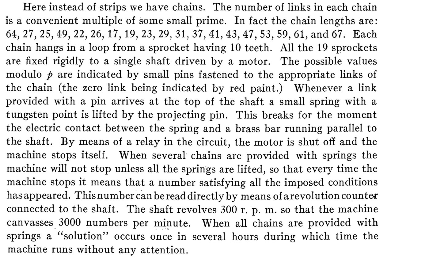
“Here instead of strips we have chains. The number of links in each chain is a convenient multiple of some small prime. In fact the chain lengths are: 64, 27, 25, 49, 22, 26, 17, 19, 23, 29, 31, 37, 41, 43, 47, 53, 59, 61, and 67. Each chain hangs in a loop from a sprocket having 10 teeth. All the 19 sprockets are fixed rigidly to a single shaft driven by a motor. The possible values modulo p are indicated by small pins fastened to the appropriate links of the chain (the zero link being indicated by red paint.) Whenever a link provided with a pin arrives at the top of the shaft a small spring with a tungsten point is lifted by the projecting pin. This breaks for the moment the electric contact between the spring and a brass bar running parallel to the shaft. By means of a relay in the circuit, the motor is shut off and the machine stops itself. When several chains are provided with springs the machine will not stop unless all the springs are lifted, so that every time the machine stops it means that a number satisfying all the imposed conditions has appeared. This number can be read directly by means of a revolution counter connected to the shaft. The shaft revolves 300 r. p. m. so that the machine canvasses 3000 numbers per minute. When all chains are provided with springs a ‘solution’ occurs once in several hours during which time the machine runs without any attention.” (LF28, p. 115)
D. N. Lehmer’s account of the same machine, written four years later as a preface to the gear sieve, adds only colour: “a crude machine was constructed of bicycle sprocket-wheels with chains of different lengths running over them. The sprocket-wheels were mounted solidly on a rotating shaft, and on certain of the links of the chains pins were fastened, which when they ran over the highest point would lift a spring and break for an instant an electrical contact. When all of the pins were in a line at the top all the contacts would be broken and the machine would stop. This machine, crude as it was, and capable of only a few hundred revolutions a minute,” gave the factors of 9,999,000,099,990,001 after two hours (D. N. Lehmer, “Hunting big game in the theory of numbers,” Scripta Mathematica 1 (1932), transcription at ed-thelen.org).
6.4.1 Shaft and sprockets
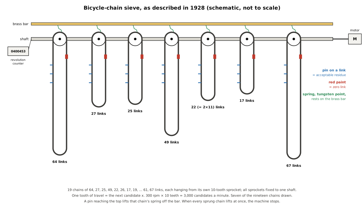
Nineteen sprockets, each with ten teeth, are “fixed rigidly to a single shaft driven by a motor.” Rigid fixing is the whole of the synchronisation scheme: because every sprocket turns with the shaft, every chain advances by exactly the same number of links per revolution — ten. Bicycle chain engages a sprocket one roller per tooth, so one tooth of rotation moves each chain by one link and advances the candidate x by one. The paper does not say where the sprockets came from, or why ten teeth; ten makes the counter arithmetic trivial, since one revolution is exactly ten candidates. The motor, its power and how it was coupled to the shaft are not recorded.
6.4.2 Nineteen chains, and why those lengths
The chain lengths are the heart of the design:
Table 1 — The chain lengths are the heart of the design
| Chain length (links) | Modulus it implements | Why that length |
|---|---|---|
| 64 | 2⁶ | Powers of 2 carry far more information than 2 alone (squares mod 64) |
| 27 | 3³ | Likewise for 3 |
| 25 | 5² | Likewise for 5 |
| 49 | 7² | Likewise for 7 |
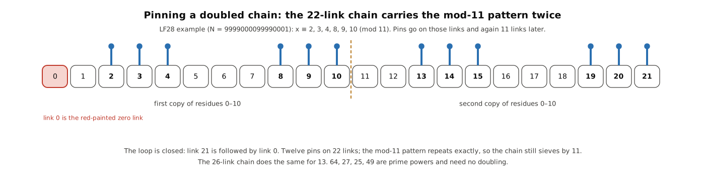
| 22 | 2 × 11 | An 11-link loop is too short to hang and run; the mod-11 pattern is repeated twice |
| 26 | 2 × 13 | Likewise for 13 |
| 17, 19, 23, 29, 31, 37, 41, 43, 47, 53, 59, 61, 67 | the primes themselves | Long enough to run as loops |
Lehmer’s phrase is “a convenient multiple of some small prime.” Huskey, who knew Lehmer for forty years, gives the reason for the doubled chains: “very short chains were not practical, so the small primes were handled by ‘composite’ chains of nonprime lengths 22, 25, 26, 27, 49, and 64 links” (Huskey). There are two different reasons hidden in that list, and a builder needs both.
Prime powers for 2, 3, 5 and 7. For the quadratic problems the machine was built for, a single small prime is a weak sieve: modulo 3 there are only two quadratic residues, so a mod-3 chain rejects at most a third of candidates. Modulo 27 or 64 the squares are much sparser, and a condition such as “a² − N must be a square” excludes far more residues. The 1928 paper shows the technique in its second example, where the conditions for 3 are worked out modulo 81 and reduced to “x = 9n + 1, 4, 7, 8” — four acceptable residues modulo 9 (LF28, p. 119). A 27-link chain can carry any condition modulo 3, 9 or 27; a 64-link chain any condition modulo 2, 4, …, 64.
Doubling for 11 and 13. Here the issue is mechanical. An 11-link loop of half-inch chain is only about 140 mm of chain in total; wrapped half round a ten-tooth sprocket it would hang barely a few centimetres and would not run smoothly. A 22-link loop carries the mod-11 pattern twice — pins at link r and at link r + 11 for each acceptable residue r — and behaves, as a sieve, exactly like an 11-link loop. The 26-link chain does the same for 13.
Taken together the chains cover every prime up to 67 — nineteen primes, nineteen chains — with the four smallest strengthened to prime powers. The moduli are pairwise coprime, so the pattern of the whole machine repeats only after 64 × 27 × 25 × 49 × 11 × 13 × 17 × 19 × … × 67 steps, about 7.9 × 10²⁸; for practical purposes it never repeats. One later source disagrees on the count: Lehmer’s 1934 paper says the chain machine considered the integers “with respect to 20 different moduli at once” (LMC34, p. 663). The 1928 list of nineteen lengths is specific and contemporary and is preferred here; the 1934 figure may count a chain whose two moduli (2 and 11 on the 22-chain, for instance) were used separately.
How long were the chains physically? LF28 gives link counts, not dimensions. Standard bicycle roller chain has a pitch of half an inch (12.7 mm), and if that was used the 67-link loop was about 850 mm of chain and the 17-link loop about 215 mm, hanging roughly 40 cm and 10 cm below the sprocket. These figures are derived, not documented.
6.4.3 Zero links and pins
Each chain’s zero link is painted red. With the machine at its starting position, every red link sits at the top, and the counter reads zero. Residue r on a chain is then the link r places from the red one, counted in the direction of travel.
The acceptable residues “are indicated by small pins fastened to the appropriate links.” The pins were improvised: Lukes, whose thesis history draws on Lehmer’s unpublished sieve log, says the pin was “a piece of chicken wire, actually” (Lukes 1995, p. 14), and kbsriram’s summary repeats “a twist of chickenwire at each accepted link” (kbsriram, A Tiny Sieve, project details). Re-setting the machine for a new problem meant untwisting and re-twisting wire on as many as half the links of nineteen chains — on the order of three hundred pins for a full set-up.
6.4.4 Springs, the brass bar and the relay
Above each chain, at the point where the chain passes over the top of its sprocket, a small spring with a tungsten point rests on a brass bar running parallel to the shaft. Tungsten is a hard, high-melting contact metal that resists pitting from repeated sparking, a sensible choice for a contact that opens hundreds of times a minute. When a pinned link reaches the top, the pin lifts the spring and “breaks for the moment the electric contact between the spring and a brass bar.”
The logic follows from the geometry. Every spring touches the same bar, so the springs are electrically in parallel: as long as any sprung chain has an unpinned link at the top, at least one spring is down and current flows through the bar to a relay. Only when every sprung chain presents a pin at once are all the springs lifted together; the circuit opens, the relay drops out, and “the motor is shut off and the machine stops itself.”
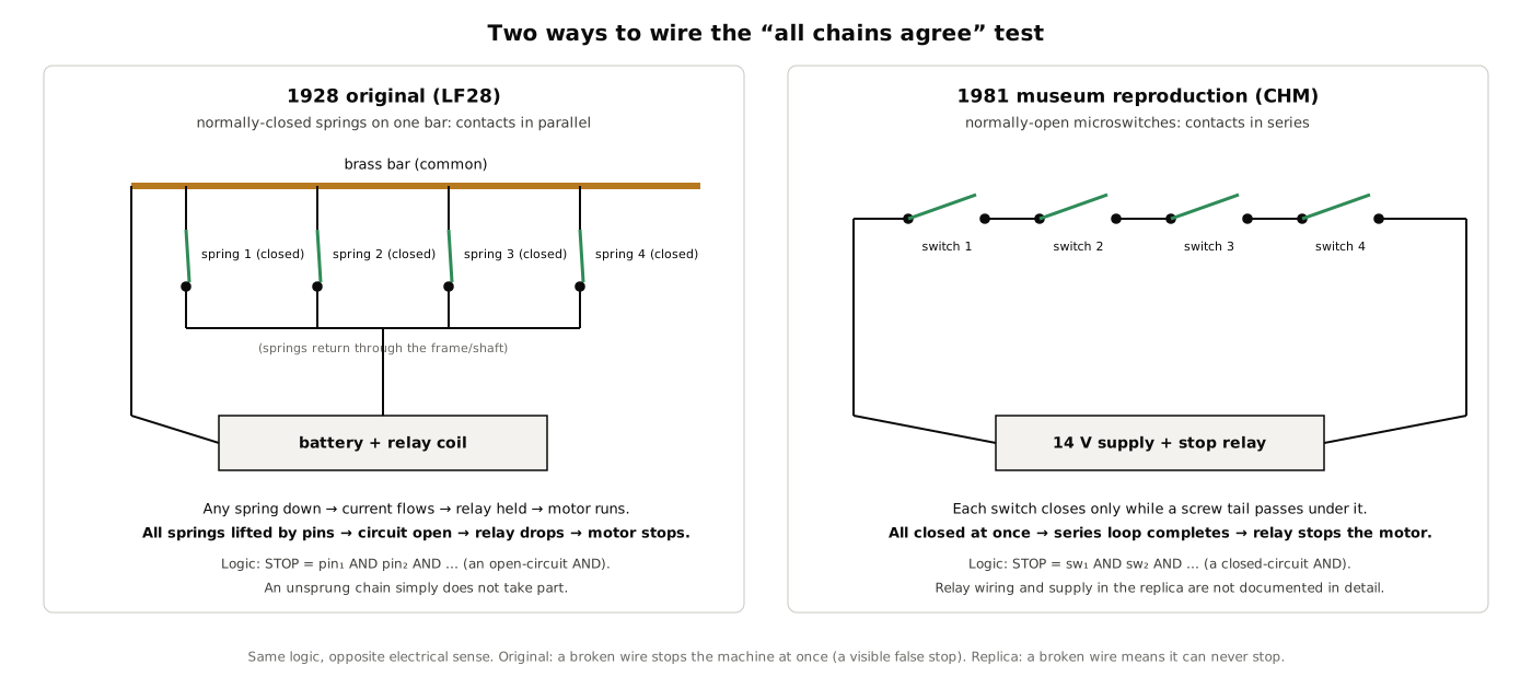
This detail is commonly reported the other way round. Lukes describes the contacts as “connected in series” with “completion of the circuit” tripping the relay, and kbsriram writes that “the switches were wired in series, so a candidate nobody rejected completed the circuit and stopped the motor” (Lukes 1995, p. 14; kbsriram, build log 2). That is an accurate description of the 1981 museum reproduction, which uses microswitches (below). It is not what Lehmer wrote in 1928, nor what his father wrote in 1932 (“all the contacts would be broken and the machine would stop”). Both arrangements compute the same thing — a logical AND over the chains — but they behave differently when something goes wrong. In the original, a broken wire or a dirty contact opens the circuit and stops the machine at once, a false stop that an operator would notice and fix. In a series arrangement, a broken wire means the circuit can never close, and the machine runs past every solution without stopping. A builder can choose either, but should choose knowingly.
The parallel arrangement has a second convenience that Lehmer used: a chain “provided with” a spring takes part in the sieve, and a chain without one does not. In the pseudosquare search he started with only the chain for 5 sprung, ran to the first non-square solution, then added the spring for 7, and so on, one modulus at a time (LF28, p. 120).
The relay’s type and coil voltage, the supply and the motor’s starting arrangement are nowhere recorded. Lehmer’s own later judgement of the electrics was unsentimental: “higher speeds of operation are impractical on account of the instability of the chains and the unreliability of the electrical contacts which are essential parts of the apparatus” (LMC34, p. 663).
6.4.5 The revolution counter
The answer “can be read directly by means of a revolution counter connected to the shaft.” Since one revolution is ten steps, either the counter was geared to read in links or the operator multiplied by ten and added the position of the red links; the paper does not say which. It also does not say how far the machine coasted after the relay cut the motor. At 50 steps a second even a fraction of a revolution of overrun moves the chains several links past the stopping position, and the operator must have turned the shaft back by hand until all the pins were again in line at the top — the procedure Lehmer describes explicitly for the gear machine in 1934 (Volume 7). For a builder this is the most important undocumented detail: plan either for a brake, or for a way to back the machine up to the stop.
6.4.6 Speed
The shaft turned at 300 rpm, ten teeth per revolution, so the machine examined 3,000 numbers a minute, or 50 a second. Some later sources give 60 a second (M. R. Williams); Lehmer’s figure is used here. Huskey’s arithmetic puts the day’s work at about 4.3 million numbers, and adds that a brute-force attack on the Mersenne number 2²¹¹ − 1 would therefore “require more than 1,070 years” — which is why every problem the machine ran was first cut down by number theory to a range of a few million.
6.5 Setting Up a Problem
LF28 is less a description of a machine than a manual for using one, and its examples show the working method in full. The pattern is always the same:
- Turn the number-theory problem into a search for an integer x in a known range.
- For each chain’s modulus m, work out which residues of x modulo m could be solutions.
- Pin those links on that chain, counting from the red link, and fit springs to the chains to be used.
- Set every red link to the top, zero the counter, start the motor, and walk away.
- When the machine stops, read x, test it by hand, and restart if it is not a solution.
6.5.1 Example 1: 9,999,000,099,990,001
The first example is the factorisation of N = (10²⁰ + 1)/(10⁴ + 1) = 9,999,000,099,990,001, a number Lehmer had already shown to be composite. To factor it as a difference of squares N = a² − b², Lehmer used what was known about its factors — they all have the form 40n + 1, and the behaviour of the continued fraction for √N suggested that 3 and 7 are quadratic non-residues of N — to show that a must have the form
a = 7200k + 7001.
The search range for a runs from √N (about 99,995,000) up to a bound set by the knowledge that N has no factor below 120,000. Substituting x = k − 13,888 gives
a = 7200x + 100,000,601, 0 ≤ x < 5,772,578,
“so that a is restricted to one case in 7200” before the machine even starts (LF28, p. 116).
For each chain, Lehmer then worked out which x make a² − N a possible square. For the excluding number 11 the calculation is shown in full: a ≡ 6x + 8 and N ≡ 1 (mod 11), and tabulating a² − N for x = 0 to 10 and discarding the non-residues leaves x ≡ 2, 3, 4, 8, 9, 10 (mod 11) — the twelve pins of the 22-link chain in the figure above. For the 49-link chain the assumption that 7 is a non-residue of N allowed a much stronger restriction, to eight residues modulo 49 instead of the usual twenty-eight: x ≡ 2, 9, 16, 23, 25, 30, 37, 44 (mod 49). “The result is that the machine will run longer between solutions” (LF28, p. 118).
“Linear forms for x were thus calculated for every excluding number ≤ 67 and the appropriate links of each chain were supplied with pins. The machine was then set in motion. After running about 2 hours it stopped itself at x = 400453,” giving a = 2,983,262,201, a² − N = 2,981,585,880², and
N = 1,676,321 × 5,964,848,081.
At 50 steps a second, 400,453 steps take 8,009 seconds — 2 hours 13 minutes, consistent with “about 2 hours.” Lehmer noted a safeguard built into the method: had the whole range been covered with no solution, that would have shown his assumption about 3 and 7 to be wrong, and the case could have been run again “without changing the position of the pins, by simply shifting the origin on each chain.”
6.5.2 Example 2: a factor of 3¹¹¹ + 1
The second example shows how fast the machine could be when the theory was good. The 17-digit number N = 20,191,210,335,106,439, a large factor of 3¹¹¹ + 1, has all its factors of the form 111n + 1, which restricts a to one class modulo 111² = 12,321, and with a ≡ 2 (mod 4) to the form a = 49,284x + 44,978,200 with 0 ≤ x < 203,943. Because 3 and 37 divide 49,284, their conditions had to be worked out differently — modulo 81, reducing to “x = 9n + 1, 4, 7, 8” on the 27-link chain. “All the linear forms were set on the chains and the machine, after running only 4 seconds, stopped at x = 145,” and
N = 25,709,599 × 78,539,161.
Lehmer’s comment is the strongest argument for the one-at-a-time machine over the strip table: “If the same problem had been attacked by the ‘movable strip’ method, the entire range would have been excluded before this solution was discovered” (LF28, p. 119). The machine was also used to prove the cofactor 64,326,272,436,179,833 prime, completing the factorisation of 3¹¹¹ + 1.
6.5.3 Example 3: a sum of two squares, and moving the origin
The third example starts from the Pell equation x² − 1721y² = −1, whose fundamental solution gives y = 76,506,518,214,341 = 17 × 4,500,383,424,373. Every factor of y is a sum of two squares, so the problem is to write N = 4,500,383,424,373 as a² + b². The excluding number 5 restricts a to 2 or 3 modulo 5, and Lehmer split the search into two cases, a = 5x + 2 and a = 5x + 3, each with 0 ≤ x < 300,013.
The first case ran its whole range with “but a single stop at x = 196113, a = 980567, N − a² = 3538871782884. This number is not a square although it is a residue of every prime ≤ 67” — a false alarm of exactly the kind the sieve cannot avoid, since the chains test only residues.
The second case shows a trick that made the chains reusable. The values of a in the two cases differ by 1 for the same x, so in terms of x the second case is the first shifted by 1/5 modulo each chain’s modulus. “On the second start therefore, instead of setting all the chains on their zero positions we set them on the link corresponding to the value of 1/5 (mod p).” No pins were moved. “This time the machine stopped only once giving x = 157044, a = 785223, b = 1970738,” so N = 785,223² + 1,970,738², and since the representation is unique, N is prime (LF28, p. 120). Splitting the work into two cases, Lehmer notes, gave the result in two-fifths of the time a single run would have needed.
6.5.4 Example 4: pseudosquares
The last problem is Kraitchik’s: find the least non-square number that is a quadratic residue of every prime up to p. Here the sieve is fighting itself, because every perfect square passes every chain. Lehmer set N = 24x + 1, pinned every chain, and then brought the chains into play one at a time by fitting their springs — 5 first, then 7, then 11 — running each time to the first non-square stop. “The squares appearing as solutions are of course squares of primes or products of primes > p. These squares were predicted in advance so as to avoid unnecessary reading of the machine.” The work was carried to p = 61, giving the least non-square 48,473,881 for p = 59 and 61 and confirming and extending Kraitchik’s hand results (LF28, pp. 120–121). Emma Trotskaia, soon to be Emma Lehmer, had worked on the same problem with D. N. Lehmer as a student (Volume 5). The pseudosquare problem returns in Volume 8, where it was the benchmark for every electronic sieve.
6.6 The Two Stops the Paper Does Not Mention
In September 2026 kbsriram re-ran the chain machine’s problems on his electronic sieve (Volume 8), clocked at the chain machine’s 50 steps a second and using nineteen of his thirty modulus cards, one for each chain (kbsriram, build log 6, “The modulus chorus plays for us”). Every solution matched, and the running times agreed with the paper’s to within half a per cent. But on two runs his sieve stopped once more than the paper reports:
- Sum of two squares, second case. LF28 says the machine “stopped only once,” at x = 157,044. kbsriram’s sieve first stopped at x = 102,151 (a = 510,758, N − a² = 4,239,509,689,809, not a square), about 18 minutes of machine time earlier.
- 9,999,000,099,990,001. LF28 records a single stop at x = 400,453. kbsriram’s sieve first stopped at x = 257,749 (a = 1,955,793,401, a² − N = 3,815,128,827,295,156,800, not a square), about 48 minutes earlier.
His argument is that “both are quadratic residues of every prime up to 67, its largest chain, and the smallest prime that rejects them is 73. So the machine would have stopped.”
The claim is checkable with a few lines of arithmetic, and it was checked for this volume. For x = 257,749, a² − N is a square modulo 64, 27, 25, 49 and every prime from 11 to 67, and x ≡ 9 (mod 49) lies inside Lehmer’s restricted set of eight residues for the 49 chain, so no chain could have rejected it; 73 is the smallest prime for which it is a non-residue. For x = 102,151 in the second sum-of-squares case, N − a² is likewise a square modulo every chain’s modulus, and again 73 is the first prime that excludes it. (For comparison, the false stop that Lehmer did report, at x = 196,113, is first excluded by 71.) A machine pinned as LF28 describes therefore had to stop at both values.
What the discrepancy means is less certain. kbsriram’s own reading is the plainest: “I’m assuming these were just left out of the final write-up.” Lehmer did report the false stop in the first sum-of-squares case, so it was not his practice to omit them, but “stopped only once” and “stopped itself at x = 400453” may describe the run that mattered rather than every halt. Other explanations — a slightly different set of pins from the one the paper’s tables imply, or a stop missed while the machine ran unattended — cannot be ruled out from the paper alone. The reproduction establishes that the stops were mathematically unavoidable; it cannot establish what happened in a Berkeley workshop in 1927.
kbsriram made a second observation that matters to anyone setting up a reproduction: on the 9,999… problem, “chains 64 and 25 accept everything, so Lehmer would have pinned every link on both these chains.” The reason is visible in the parametrisation. The multiplier 7200 = 2⁵ × 3² × 5² is divisible by 25, so a mod 25 never changes as x increases, and 7200 ≡ 32 (mod 64), so a mod 64 takes only two values; once the form 7200x + 100,000,601 has been chosen, those chains have nothing left to exclude. The same thing happens on many problems, and a fixed set of chain lengths can do nothing about it. Lehmer made exactly this point, decades later, in arguing for adjustable sieves (Volume 8).
6.7 What the Machine Could Not Do
The chain sieve’s limits are clear from its own paper. It could only exclude: every stop, true or false, needed a human check, and on problems such as pseudosquares the false stops (the perfect squares) had to be predicted in advance and skipped. It had nineteen fixed moduli, and the largest was 67, so any survivor that happened to be a residue of every prime up to 67 — an event that becomes common over a long enough range — would stop it. At 50 steps a second its practical range was a few million candidates per run, which is why the paper’s examples all begin with careful theory that narrows the search by a factor of thousands before a single pin is placed. And its reliability set its speed: chains whip and stretch, and break-contacts bounce. “Higher speeds of operation are impractical,” Lehmer wrote, which is why his next machine had no chains and no contacts at all.
6.8 The 1981 Reproduction
When Lehmer gave his sieves to The Computer Museum in Boston in 1982, the chain machine was the one that no longer existed. The museum built one. The Spring 1983 Computer Museum Report shows “the Museum’s working model before the installation of micro-switches and a counter” and credits Roberto Canepa, Andrew Kristoffy and Richard Rubinstein with the replication (R. Rubinstein, “D. H. Lehmer’s Number Sieves,” The Computer Museum Report, Spring 1983, p. 4). The finished machine is now at the Computer History Museum in Mountain View, catalogued as “Lehmer Bicycle Chain Number Sieve,” made 1981, manufacturer “DH Lehmer / Robert Canepa” (CHM catalogue 102647620).
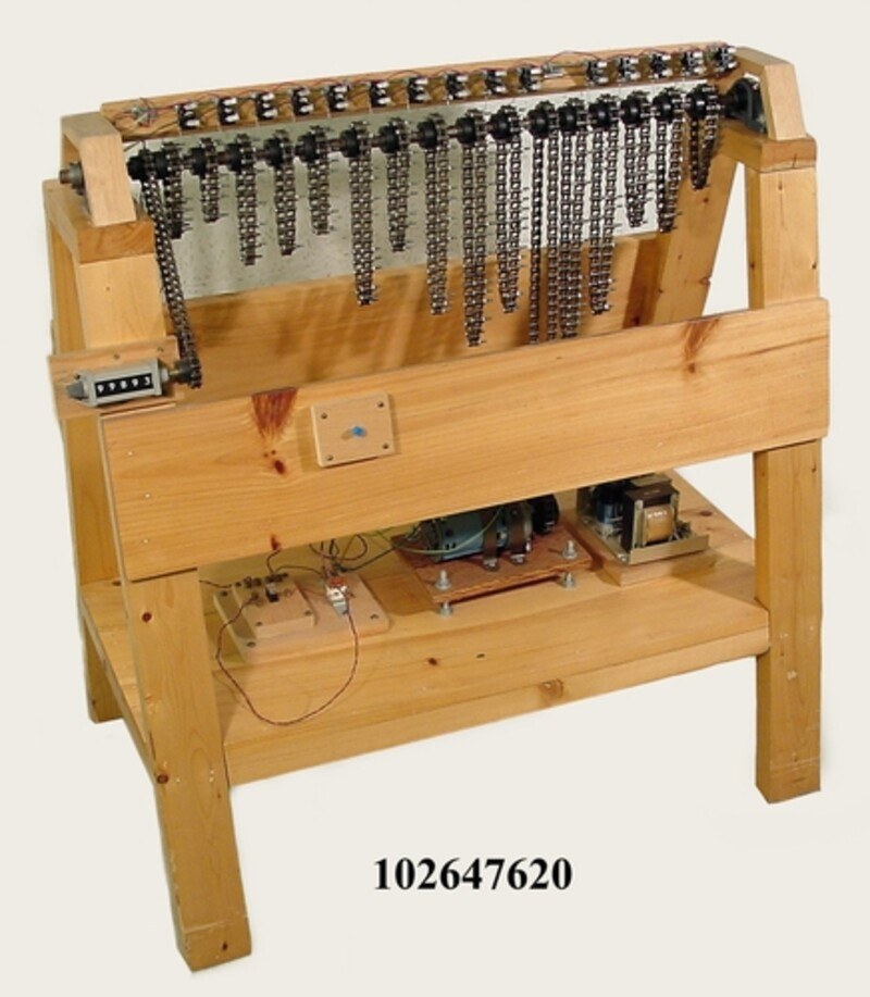
The museum’s catalogue entry is the best physical description of any Lehmer chain machine:
“The frame is similar in shape to a sawhorse. At the top is a shaft with 17 sprockets. One of the sprockets is attached to a chain which connects it to a motor affixed to the bottom of the unit. Another sprocket has a chain that goes to a mechanical revolution counter at the left side of the unit. The remaining sprockets have loops of bicycle chain of varying lengths. In each chain, some of the pivots have been replace[d] with screws with long tails. There is a micro-switch mounted above each of these chains which is activated when one of the long screw tails passes by. The frame that the switches are attached to flips up. There is a blue push button mounted on the front of the frame halfway up. There is a 14 V power supply attached to the bottom of the unit.” (CHM catalogue 102647620)
The machine weighs 85 lb and measures 39 in wide, 38½ in high and 23½ in long (99 × 98 × 60 cm).
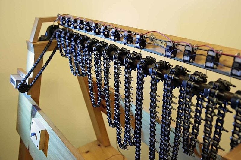
The reproduction is a faithful demonstration of the principle and a different machine in detail. Readers and builders should keep the two apart:
Table 2 — The reproduction is a faithful demonstration of the principle and a different machine in detail. Readers and builders should keep the two apart
| Feature | 1926–27 original (LF28, 1928) | 1981 reproduction (CHM) |
|---|---|---|
| Chain loops | 19 | 15 (17 sprockets, two of which drive the motor link and the counter) |
| Chain lengths | 64, 27, 25, 49, 22, 26, 17 … 67 | Not recorded in the catalogue |
| Residue markers | Small pins on links — twists of chicken wire | Chain pivots replaced by screws with long tails |
| Sensors | Springs with tungsten points resting on a brass bar | One microswitch per chain on a flip-up frame |
| Contact sense | Normally closed, in parallel; machine stops when all open | Normally open, in series (per Lukes); stops when all close |
| Counter | Revolution counter on the shaft | Mechanical revolution counter driven by its own chain |
| Drive | Motor on the shaft, 300 rpm | Motor at the base, chain-coupled |
| Power | Not recorded | 14 V supply |
| Survives | No — dismantled c. 1928 and stolen | Yes, Computer History Museum |
The microswitches also explain the “series” description that runs through later literature: a microswitch is the natural modern component, and a normally-open switch pressed by a passing screw tail is most simply wired in series.
6.9 What a Builder Can Rely On
For a reconstruction — Volume 11’s subject — the record supports the following with confidence: nineteen chains of 64, 27, 25, 49, 22, 26, 17, 19, 23, 29, 31, 37, 41, 43, 47, 53, 59, 61 and 67 links; one ten-tooth sprocket per chain, all fixed to one motor-driven shaft; a red zero link on each chain; pins on the acceptable residues; a spring contact per chain resting on a common bar, lifted by the pins; a relay that stops the motor when every contact opens; a revolution counter on the shaft; and a speed of 300 rpm, or 50 candidates a second. Huskey’s statement that the 22- and 26-link chains exist because short chains were impractical, and Lukes’s chicken wire, are good secondary evidence.
The record does not give: the chain pitch (ordinary half-inch bicycle chain is the natural assumption), the frame, the sprocket source, the relay and supply, the motor, how the counter was geared, how much the machine coasted after a stop, or how the operator backed it up to read the answer. Those are design decisions for the builder, and they should be recorded as such. The five problems of LF28, with kbsriram’s two extra stops, make a complete acceptance test: a correct reproduction must stop at x = 145 on the 3¹¹¹ + 1 factor, at 196,113 and then nowhere else on the first sum-of-squares case, at 102,151 and 157,044 on the second, and at 257,749 and 400,453 on 9,999,000,099,990,001. Volume 14 runs that test.
Two often-repeated claims do not belong to this machine. The factorisation of 2⁹³ + 1 “in 3 seconds,” attributed to the chain sieve in some summaries, was done in 1932 on the photoelectric gear sieve (Volume 7). And the “series microswitches” belong to the 1981 reproduction, not to the original.
Next — Volume 7: The Photoelectric Gear Sieve (1932). Thirty steel gears drilled under every tooth, toothpicks in the holes, an automobile headlamp, a photocell and an amplifier with a gain of seven hundred million that a neighbour’s short-wave radio could set off: Lehmer’s answer to the chains’ limits, a hundred times faster, and still in the Computer History Museum.
Comments (0)