Number Sieves · Volume 7
Number Sieves — Volume 7 — The Photoelectric Gear Sieve (1932)
Thirty gears drilled under every tooth, toothpicks in the holes, a headlamp, a photocell and an amplifier with a gain of seven hundred million: how D. H. Lehmer's second machine worked and what it found
7.1 About This Volume
The bicycle-chain sieve of Volume 6 proved that a machine could combine congruences faster and more reliably than a person with paper strips, and it also showed where the method’s limits lay: chains whip and stretch, spring contacts bounce, and fifty candidates a second is as fast as such a machine can safely run. In 1932 D. H. Lehmer replaced both the chains and the contacts. His second machine has thirty steel gears, one per modulus, each drilled with a hole under every tooth; holes at unacceptable residues are plugged; and a beam of light passes through the whole stack only when every gear presents an open hole at once. A photocell and a vacuum-tube amplifier turn that flash into a signal that stops the motor. It ran at 5,000 candidates a second — a hundred times the chain machine — and it survives, in the Computer History Museum.
This volume describes the machine from the sources nearest to it: Lehmer’s own technical description in Mathematische Annalen (1934), his announcement of results in the Bulletin of the American Mathematical Society (1933), his father’s essay of 1932 describing the first demonstration, Lehmer’s 1973 oral history, the Computer Museum’s 1983 exhibit report, and photographs of the surviving artifact. It works through the problems the machine solved, compares the record with modern summaries — which disagree with Lehmer on the gears’ tooth counts and on the date of the Chicago exhibition — and sets out what a builder can and cannot learn from the record. Volume 12 turns this into a build procedure; the shared fact sheet is 05-resources/machine-facts.md.
One source this volume could not read is Lehmer’s own article “A photo-electric number sieve,” American Mathematical Monthly 40 (1933) 401–406 (doi:10.1080/00029890.1933.11987465), which is paywalled and has no open copy. Where later writers quote it, the quotation is identified as theirs. Its short corrigendum in the December 1933 issue of the same journal (doi:10.2307/2301705) was not read either.
7.2 Why a New Machine
Lehmer explained the change in one sentence about the chain machine: “Higher speeds of operation are impractical on account of the instability of the chains and the unreliability of the electrical contacts which are essential parts of the apparatus” (D. H. Lehmer, “A machine for combining sets of linear congruences,” Math. Annalen 109 (1934) 661–667, p. 663, cited below as LMC34). The new design removed both. Gears are rigid where chains are not, and rotate about their own centres, so they can turn fast without flailing. Light needs no contact at all. “We owe the achievement of this high rate of speed to modern physics,” he wrote, “for the photoelectric cell and the thermionic valve are indispensable elements of the machine.”
The idea of holes and light was not new. Maurice Kraitchik had built a wooden gear sieve with holes and a lamp in 1912, its solutions shown as a spot of light on a screen to be watched by eye (Volume 5). What Kraitchik lacked was a detector fast enough to stop a machine on a flash lasting a ten-thousandth of a second. In 1932 that was at the edge of what electronics could do.
7.3 Who Built It, and Where
Lehmer described the division of labour himself in 1973: “when I was at Brown I designed this photo electric sieve which was a factor of a thousand faster than the other machine I had. So part of my postdoctoral work was to build this photo-electric sieve which I built myself partly and with the help of R.C. Burt Engineering in Pasadena who did the electronics on it. I did the mechanical part. And it all came together in 1932 here” (D. H. Lehmer, oral history interview, 18 April 1973, Smithsonian/AFIPS, pp. 2–3). (The factor was in fact one hundred: 50 candidates a second to 5,000.) Lehmer held a National Research Council fellowship at the California Institute of Technology in 1930–31 and at Stanford in 1931–32, which puts the machine in Pasadena and the Bay Area.
The money came from the Carnegie Institution of Washington, which had published D. N. Lehmer’s tables. MacTutor quotes a contemporary newspaper report of “the grant of $1,000 to Dr Derrick N Lehmer of the Mathematics Department of the University of California,” for a machine “to be constructed under Professor Lehmer’s direction by his son Derrick H Lehmer, national research fellow” (MacTutor, Derrick Norman Lehmer). D. N. Lehmer’s own essay credits “the generous cooperation of the Carnegie Institution of Washington” (D. N. Lehmer, “Hunting big game in the theory of numbers,” Scripta Mathematica 1 (1932) 229–235, transcription at ed-thelen.org, cited below as HBG32).
The surviving machine is catalogued by the Computer History Museum as “Photoelectric Number Sieve Machine (‘Gear Machine’),” made 1932, one of one, 275 lb, “Gift of D. H. Lehmer,” with the note that “the machine also had a photo detector and powerful amplifier which was not included in the gift” (CHM catalogue X85.82). The catalogue lists the maker as “D. H. Lehmer / Robert Canepa”; Canepa, who built the museum’s chain-sieve reproduction in 1981, presumably prepared the machine and its separate motor base for display.
7.4 October 1932: The First Runs
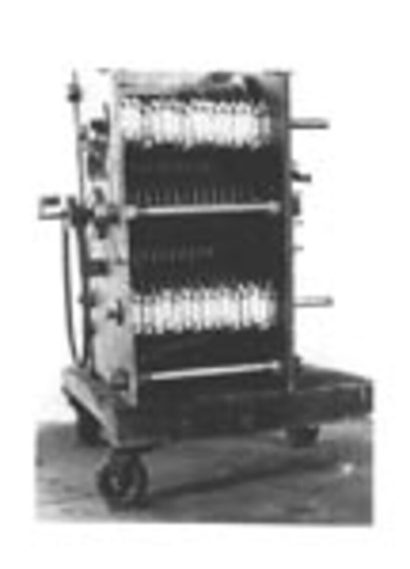
D. N. Lehmer’s essay “Hunting big game in the theory of numbers” is the only eyewitness account of the machine’s first weeks, and it is a vivid one. It opens on “the 19th of October,” when “a little group of mathematicians gathered in the Burt Laboratories in Pasadena, California, around a mysterious machine to watch it attack a problem”: to find two numbers whose product is 5,283,065,753,709,209.
“‘Here we step out into the unknown!’ said the young inventor as he threw the switch and set whirling a complicated mass of gears. It was of no use for the human eye to try to make anything out of the rapidly rotating wheels. One might as well try to identify the teeth on a buzz-saw. Besides it was quite unnecessary, for a fixed, unwinking eye was turned on the machine waiting for a ray of light to slip through certain holes in the wheels.” (HBG32)
Asked how fast it was working, “about a hundred thousand a minute,” the young man answered; “with a larger driving motor we could make it in twenty minutes. The electric eye would catch it if it were going five times as fast.” Then “Suddenly, click! The power was shut off … The machine was turned slowly back till a tell-tale beam of light appeared through the little hole,” a few minutes’ work with a desk calculator found the number as a square plus seven times a square, and the machine was restarted for a second representation. That took twenty-five minutes, during which “one of the mathematicians at least, the father of the young inventor, was in something of a state of nerves.” The two representations gave the factors 59,957 × 88,114,244,437 “while coffee was being served on one of the working tables in the laboratory.” The point of the exercise was a larger number: with M factored, Lehmer could complete a primality proof for 3,011,347,479,614,249,131, the large factor of 2⁹⁵ + 1.
The essay also records the machine’s first real result, ten days earlier. “On the 9th of October, just after the discovery of the ‘imp,’” the machine was set on the 19-digit cofactor of 2⁹³ + 1, known to be composite but with no factor below 300,000. “The amplifier woke up and threw off the power after only a few seconds of work, and it was thought, of course, that the ‘imp’ was on the air again.” It was a real stop. “The work of a quarter of a century had been done in less than a quarter of a minute.”
The “imp” is the best-known story about the machine. The amplifier, sensitive enough to be upset by “a slight jar, an infinitesimal variation in the electric current, the turning off of an electric appliance or even a hasty word from an attendant,” was moved “in another room separated from the whirling gears by a heavy brick wall, and was enclosed in a coffin of celotex” — a fibreboard sold as acoustic and thermal insulation. It still threw unpredictable fits. “At last it occurred to him to use a stethoscope. He installed a loud speaker and ‘listened in.’ Instantly the hiding place of the ‘imp’ was discovered. There was a short-wave radio fan operating in a station in the immediate neighborhood.” Until the amplifier could be screened, the only remedy was “to wait till the ether was quiet before asking the machine any important arithmetical questions” (HBG32).
The essay’s printed date — Scripta Mathematica, September 1932, according to the transcription — sits awkwardly with events of 9 and 19 October. The issue probably appeared late; Williams and Shallit cite the volume as “1 (1932/33).” The year of the events is not in doubt, since Lehmer’s Bulletin note of February 1933 reports the same factorisations as “the result of a month’s experiment with the machine” (D. H. Lehmer, “Some new factorizations of 2ⁿ ± 1,” Bull. Amer. Math. Soc. 39 (1933) 105–108, cited below as NF33).
7.5 The Mechanism
Lehmer’s 1934 description is the fullest technical account he published, and like the 1928 one it is short enough to read whole.
“To obtain high speeds the mechanical system has been made as simple as possible. There are only 31 moving parts and these are gears rotating about their centers of gravity. There are 30 driven gears, all driven at the same linear speed of about 1700 meters per minute by a single driving gear. The 30 driven gears correspond to 30 moduli and have for numbers of teeth convenient multiples of every prime < 127. The largest gear has 128 teeth and the smallest 67 teeth. At the base of each tooth on each driven gear, holes are drilled at a constant distance from the periphery of the gear, this distance being the same for all gears. These holes are about 2 millimeters in diameter and correspond to the numbers 0, 1, 2, …, p − 1 modulo p. If x is to be restricted to a set of s numbers modulo p the holes corresponding to these numbers are left open, while the other holes are stopped up with wooden pins. The gears are mounted parallel to one another and have a common line of tangency so that if a beam of light from an incandescent lamp shines through a hole in any gear it is transmitted or blotted out by the next gear.” (LMC34, p. 663)
7.5.1 Gears and drive
Thirty driven gears, one per modulus. The primes below 127 are exactly the thirty primes from 2 to 113, so “every prime < 127” means one gear for each of them. Every gear is driven “at the same linear speed,” which is the gear equivalent of the chain machine’s rigid shaft: because all the gears have the same tooth pitch and mesh with the same drive, each advances by exactly one tooth per step regardless of its size. A gear of m teeth therefore returns to its starting position every m steps, exactly as a chain of m links does.
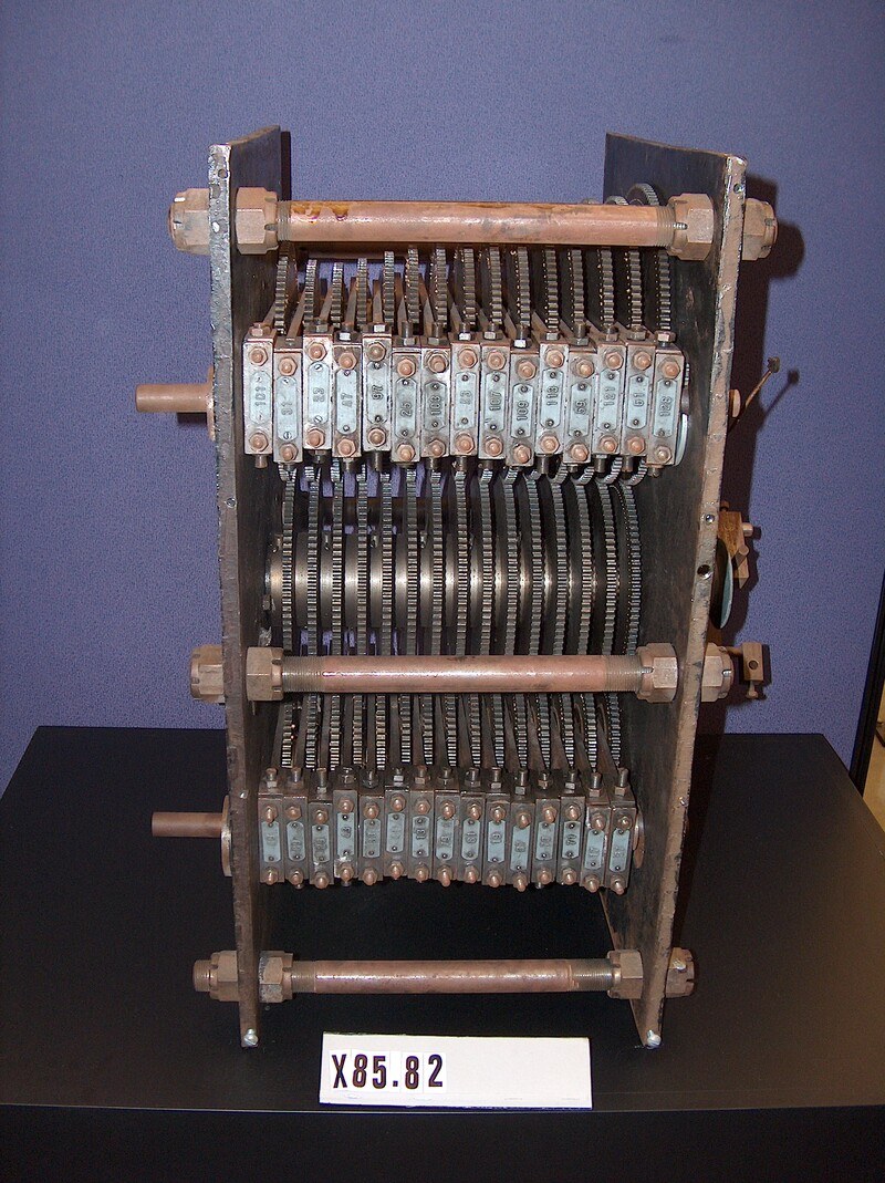
One driving gear — in practice, a driving shaft. “Only 31 moving parts” counts the drive as one. Lukes’s history describes it more concretely: “The 15 driving gears all had 100 teeth and were mounted on a common shaft. Each of the 30 modulus gears had an individual axle and meshed with one of the driving gears. The gears were arranged in two sets of 15 on either side of the driving gears with two modular gears engaging one driving gear” (R. F. Lukes, A Very Fast Electronic Number Sieve, PhD thesis, University of Manitoba, 1995, p. 15). The photographs agree: the surviving machine has an upper bank of fifteen gears in labelled bearing blocks, a central row of driving gears on one shaft, and a lower bank of fifteen. Fifteen drivers fixed to one shaft are, mechanically, one part. (The 1931–32 newspaper description of the planned machine, quoted by MacTutor, speaks of “thirty gears of 100 teeth each” on the shaft; the built machine evidently halved that by letting each driver serve two modulus gears.)
Speed. The machine examined “the natural numbers with respect to 30 moduli at once at the rate of 300 000 numbers per minute” — 5,000 a second (LMC34, p. 663). At the first demonstration it ran at about a third of that, a hundred thousand a minute, with a smaller motor (HBG32).
What the numbers imply. Lehmer gives the linear speed (about 1,700 metres a minute) and the step rate (300,000 a minute) but not the gear size. Dividing one by the other gives a tooth pitch of about 5.7 mm, which is a coherent design: a 128-tooth gear would then be about 23 cm across and a 67-tooth gear about 12 cm, a 100-tooth driver about 18 cm, and the drivers would turn at 50 revolutions a second, or 3,000 rpm. These are derived figures, not measurements, but they agree with the photographs in proportion. The often-repeated “20 feet per second” for the gear rim was not found in any source consulted for this series; Lehmer’s figure is about 93 feet per second.
7.5.2 Holes and toothpicks
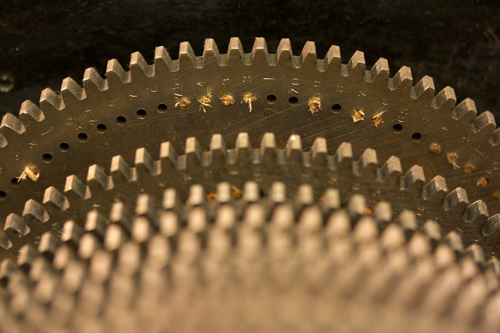
Under each tooth, at the same radius on every gear, is a hole about 2 mm across; residue r is the hole under tooth r. To set a problem, the operator stops up the holes at excluded residues “with wooden pins.” Other sources say toothpicks (M. R. Williams; the 1983 Computer Museum report), and close-up photographs of the surviving machine show the stubs of wooden plugs still in the holes.
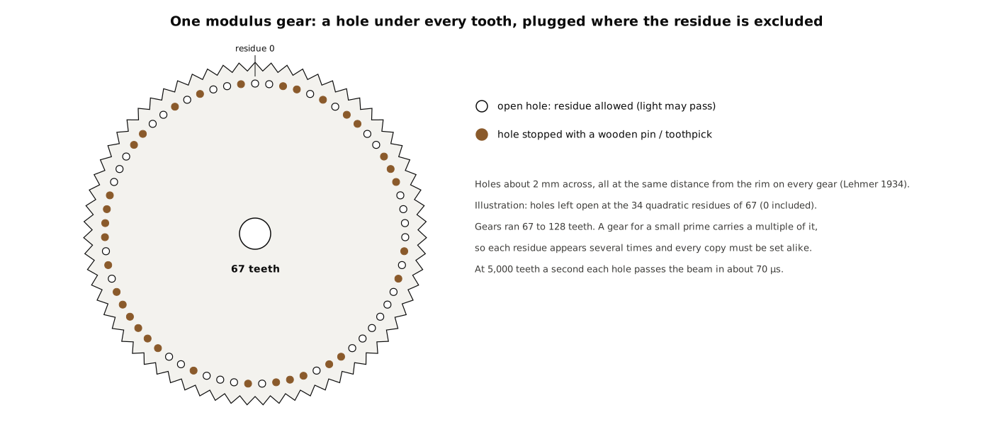
Setting up was slow. Lukes, citing A. J. Stephens’s 1989 thesis, says “loading a complete problem took over two hours” (Lukes 1995, p. 15). Thirty gears of 67 to 128 holes is about 3,000 holes, of which roughly half are plugged for a typical quadratic problem.
7.5.3 The tooth counts, and a disagreement
What exactly were the thirty tooth counts? Here the sources part company, and a builder needs to know why.
Lehmer’s own description says only that the teeth are “convenient multiples of every prime < 127,” that “the largest gear has 128 teeth and the smallest 67 teeth.” Since every gear has at least 67 teeth, the twelve primes from 67 to 113 can each have a gear of exactly that many teeth, but the eighteen smaller primes need multiples: 2 needs 128 = 2⁷ (64 would be too small), 3 a multiple such as 81 = 3⁴, 11 a multiple between 77 and 121, 13 one of 78, 91, 104 or 117, and so on up to 61, which needs 122. The worked example in the same paper uses “the moduli 9, 25, 49 and 121 instead of 3, 5, 7, and 11” — and a condition modulo 121 can only be set on a gear whose tooth count is a multiple of 121, which within the 67–128 range means 121 itself (LMC34, p. 665).
The surviving machine carries a small engraved label on each bearing block. Photographs by Marcin Wichary show the upper bank, left to right, labelled 101, 31, 23, 47, 97, 25, 103, 53, 107, 109, 113, 59, 121, 61, 128, and part of the lower bank labelled …, 41, 13, 79, 81, 19, 37, …. The labels for the four smallest primes read 128, 81, 25 and 121. (A label for 7 was not visible in any photograph examined.) Whether a label gives the tooth count or the largest modulus the gear can carry is not recorded; “25” cannot be a tooth count, since no gear has fewer than 67 teeth, so the labels are most likely moduli — a 25-labelled gear would then have 75 or 100 teeth.
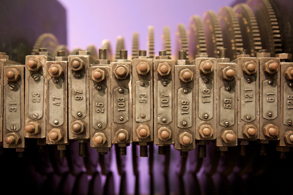
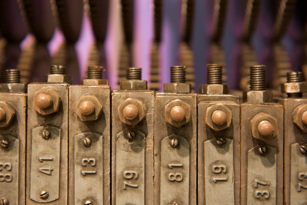
Modern summaries give a different list. Lukes’s history says the sieve “had gears representing 64, 27, 25, 49 and the primes from 11 to 113” (Lukes 1995, p. 15), and kbsriram, citing Lehmer’s 1933 Monthly article, writes that “the first four gears in the machine had prime power tooth counts (64, 27, 25, 49, not 2, 3, 5, 7) with the rest being the primes 11 through 113” (kbsriram, A Tiny Sieve, project details). Volume 4 of this series repeats that list from kbsriram. It cannot be right as a list of tooth counts, because 64, 27, 25, 49 and the primes 11 to 61 are all below Lehmer’s stated minimum of 67 teeth, and it does not match the labels on the machine. It may be a list of the moduli Lehmer usually used — the chain machine’s 64, 27, 25, 49 carried over — or it may reflect what the unread 1933 article says; that article was not available to check.
The safest statement is therefore: thirty gears, one for each prime from 2 to 113; teeth between 67 and 128, each a multiple of its prime; gears for 2, 3 and 11 labelled 128, 81 and 121, and the gear for 5 labelled 25; the per-gear tooth counts were not found in any source consulted. For a reconstruction, Volume 12 has to choose a set — and anyone with access to the machine at the Computer History Museum could settle it by counting teeth.
7.5.4 The machine’s period
The disagreement matters for one number kbsriram examined. According to him, the 1933 Monthly article gives the machine’s period — the number of steps before every gear returns to its starting tooth — as
2,497,194,316,592,991,015,263,471,297,031,949,336,968,700,272,210.
That number is exactly the product of the thirty primes from 2 to 113, with 79 multiplied in a second time; this was checked for this volume. kbsriram’s point is that the gears were not tooth counts 2, 3, 5, 7, so the product of primes cannot be the period, and that with tooth counts 64, 27, 25, 49 and 11 to 113 the period would be 318,629,350,775,409,486,504,503,679,418,760,117,932,208,844,859,200, about 128 times larger (kbsriram, build log 6). The arithmetic of both numbers is correct, and his central observation — that the published period cannot be right for a machine whose small-prime gears are prime powers — stands. But if the tooth counts are those Lehmer gives in 1934 (all between 67 and 128) the true mechanical period is the least common multiple of those thirty counts, which is different again and cannot be computed without them. The December 1933 corrigendum to the Monthly article may bear on this; it was not read.
7.6 The Light Path
The optical system is the machine’s invention. The gears are “mounted parallel to one another and have a common line of tangency,” so that one straight line passes through the hole circle of every gear at the same angular position. A lamp at one end shines along that line. “If the driving gear is rotated (from some zero position) until x teeth have turned past and if x satisfies the conditions imposed by all the moduli, then there will be an alignment of open holes and the beam of light will traverse the system of gears. However, if x fails to satisfy the conditions imposed by a certain modulus, the corresponding gear will prevent the passage of light” (LMC34, pp. 663–664).
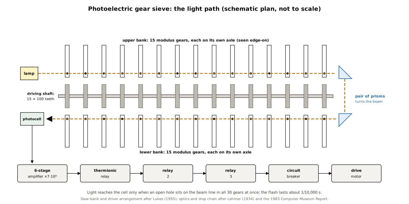
Three details complete the picture:
- The lamp. Lehmer says “an incandescent lamp.” The 1983 museum report says the light was “originally supplied by an automobile headlight lamp” (R. Rubinstein, “D. H. Lehmer’s Number Sieves,” The Computer Museum Report, Spring 1983, p. 2) — a compact, bright filament designed to be focused, and cheap.
- Prisms. With two banks of gears on opposite sides of the driving shaft, a single straight beam cannot pass through all thirty. Lukes says “a pair of prisms” redirected the beam from the first set of fifteen to the second (Lukes 1995, p. 15). The arrangement of lamp, prisms and cell relative to the banks is not documented in any source read; the figure shows one consistent possibility.
- The flash. “The amount of light which succeeds in getting through the 30 gears is very small and it lasts only a ten thousandth of a second” (LMC34, p. 664; D. N. Lehmer gives the same figure). That figure is consistent with the mechanism: at 5,000 steps a second each tooth passes in 200 microseconds, and a 2 mm hole on a 5.7 mm pitch is fully open on the beam for a fraction of that, of the order of 70 microseconds.
7.7 From Flash to Stop
“In order to observe and report the appearance of this tiny flash of light, a photo-electric cell is placed behind the last gear … the photo-electric cell is very inefficient. The energy produced by the cell must be sufficiently magnified to operate a circuit breaker to stop the electric motor driving the machine. This is done by means of a six stage amplifier. The amplifier magnifies the energy from the photoelectric cell by a factor of 700000000. This much energy is sufficient to operate a delicate thermionic relay, the first of a series of three relays which finally stops the machine.” (LMC34, p. 664)
D. N. Lehmer gives the gain as 729,000,000 (HBG32) — exactly 30⁶, a gain of 30 in each of six stages — and the 1983 museum report repeats Lehmer’s 700,000,000. The chain of events is therefore photocell, six-stage vacuum-tube amplifier, thermionic relay (Lehmer does not describe it further), two further relays, and a circuit breaker on the drive motor. None of the electronics survives with the machine, and R. C. Burt’s circuit was never published.
Michael R. Williams, curator at the Computer History Museum, adds a claim that circulates widely: that the light “would trip a flip-flop attached to the photocell — perhaps the first time that an electronic flip-flop was used in a computing device (they had been used earlier in counters for cosmic rays and this is what gave Lehmer the idea)” (M. R. Williams, “Lehmer Sieves”). Lukes’s footnote attributes the same suggestion to Lehmer’s 1980 history. A latching trigger is the natural reading of Lehmer’s “thermionic relay”: a device that turns a 100-microsecond flash into a state that persists until reset. The claim of priority could not be checked.
7.7.1 Reading the answer
The stop is not instant. The machine “coasted many thousands past a ‘hit’” (H. Huskey, IEEE Computer Pioneers), so the operator had to find the stopping place by hand: “He then substitutes the human eye for the photo-electric cell, and by reversing the machine very slowly, brings it back to the exact position where the light shines through. He then reads the number of teeth by means of a revolution counter. This number is then the smallest positive integer satisfying the conditions of the 30 moduli. If it is not an answer to our problem the machine is set in motion again” (LMC34, p. 664). D. N. Lehmer’s account of the demonstration describes exactly that: “The machine was turned slowly back till a tell-tale beam of light appeared through the little hole.” Between stops, the operator “needs to give it no further attention until, on one of his occasional visits to the laboratory he finds that the machine has stopped.”
7.8 What It Solved
The Bulletin note of February 1933 announced five factorisations of numbers of the form 2ⁿ ± 1, all “the result of a month’s experiment with the machine. As a matter of fact the machine ran only a few hours altogether” (NF33, p. 105). The machine solved three of them directly and supplied the key factorisation for two primality proofs.
7.8.1 2⁹³ + 1
Lehmer worked this example in full in 1934, as a demonstration of method. The cofactor is
N = (2⁹³ + 1)(2 + 1)/((2³¹ + 1)(2³ + 1)) = 1,537,228,672,093,301,419,
known to have no factor below 300,000. Every factor of N has the form 93x + 1 and 8x ± 1 or 3, which forces a in N = a² − b² into the form a = 69,192x + 1,239,854,518 with 0 ≤ x ≤ 37,010,176. The condition is that
f(x) = 4,787,532,864x² + 171,576,027,618,912x + 10,553,711,710,905
be a perfect square, and Lehmer’s tables gave, for each prime and prime power up to 127, the values of x for which f(x) is a quadratic residue — for example x ≡ 0, 1, 2, 9, 10, 11 (mod 13) — using the moduli 9, 25, 49 and 121 in place of 3, 5, 7 and 11. “To present this problem to the machine we have only to stop up the holes in each gear which correspond to those values of x not listed above … In this example the machine stopped in about 3 seconds at x = 6886,” where f(6886) = 1,186,799,691², giving a = 1,716,310,630 and
N = 529,510,939 × 2,903,110,321,
and 2⁹³ + 1 = 3² · 529,510,939 · 715,827,883 · 2,903,110,321 (LMC34, pp. 664–666; NF33, p. 107). This is the “factored in three seconds” result that some summaries attach to the chain sieve; it belongs to this machine.
7.8.2 2⁷⁹ − 1
For N = (2⁷⁹ − 1)/2687, the forms of the factors gave eight possible residue classes for a modulo 9,586,176, so “the problem of representing N as the difference of squares was split into 8 parts. The first two parts were covered by the machine without any result. On the third run, however, the machine stopped almost at once at x = 58088,” giving
2⁷⁹ − 1 = 2687 × 202,029,703 × 1,113,491,139,767,
“the 13th composite Mersenne number to be completely factored” (NF33, pp. 107–108). kbsriram reports that the 1933 Monthly article gives the running time as 12 seconds; that source was not read.
7.8.3 2⁹⁵ + 1, and M = 5,283,065,753,709,209
The third factorisation was the one demonstrated at Burt Laboratories. To prove the 19-digit cofactor N = 3,011,347,479,614,249,131 of 2⁹⁵ + 1 prime, Lehmer needed a large prime factor of N − 1 = 2 · 3 · 5 · 19 · M, where M = 5,283,065,753,709,209. A continued-fraction expansion showed −7 to be a quadratic residue of M, so a composite M should have two representations as x² + 7y². “The machine gave them in less than half an hour”:
M = 40,923,451² + 7·22,704,112² = 66,855,539² + 7·10,779,628²,
whence M = 59,957 × 88,114,244,437, and with the second factor proved prime the primality of N followed (NF33, p. 106). Lehmer added that the machine “could have been easily set to search directly for the factors of N, but its failure to find a factor might not have been acceptable to the reader as a proof of primality.” The cofactors of 2⁷³ + 1 and 2⁸⁵ − 1 were proved prime by the same theorem.
7.8.4 False stops and the pseudosquare problem
Like the chains, the gears could only exclude. Lehmer gives an example of an extraneous stop “in another problem”: the machine delivered 3,644,964,042,849,448,987,514,933,241, “a residue of every prime and power of prime < 137. It is not a square however.” Such numbers — non-squares that behave like squares for every small prime — are exactly the pseudosquares of Volume 6, and Lehmer noted that the same property made them hard to hunt on this machine: perfect squares pass every gear, and “these undesirable squares occur so frequently at first that it is impractical to use the new machine for x < 50000000” (LMC34, p. 666).
7.8.5 How much faster than a person?
Lehmer declined to give a single figure: “If the answer is small, the machine will find it at once. In the worst case, the machine must canvass a certain range of natural numbers … On this assumption the machine can do in 20 minutes what the computer can do in a year.” But a skilled human “computer” splits a problem into cases and can gain “a factor of 100 or even more,” so “a truer estimate of the value of the machine is obtained by considering the number of problems it can solve, that have thus far withstood the attacks of our best arithmeticians” (LMC34, pp. 666–667). D. N. Lehmer’s version was more colourful: about ten million candidates, at six minutes each, “comes to sixty million minutes, or about a million hours … One could do it in three hundred years if he did not get stale” (HBG32).
7.9 Re-running the Problems in 2026
kbsriram’s electronic sieve (Volume 8) re-ran the gear machine’s problems with all thirty of its modulus cards and its step clock set to the gear machine’s 5,000 a second. On 2⁷⁹ − 1, his parametrisation stopped once, at x = 56,523, after 11.31 seconds — against the 12 seconds he reports from the 1933 article; on 2⁹³ + 1 it stopped once, at x = 6,886, after 1.41 seconds, matching Lehmer’s x exactly and his “a few seconds” (kbsriram, code/06/results.md; build log 6). He also observed that “on 2⁷⁹ − 1, moduli 64, 27 and 79 accept every candidate, so those three gears played no part in the sieving” — on fixed hardware, some gears inevitably do nothing for some problems. (His x-value for 2⁷⁹ − 1 differs from Lehmer’s 58,088 because the search was set up differently; both lead to the same factors.)
7.10 The Chicago Exhibition
That the machine was shown at Chicago’s Century of Progress International Exposition is well attested: Lehmer said so, Huskey and Williams say so, and the back of the Computer History Museum’s photograph is labelled “DH Lehmer First photoelectric sieve, 1932, as it appeared, at the Century of Progress Exposition in Chicago” (CHM catalogue 102626132). The year is the problem. Lehmer’s own recollection in 1973 was “It was next assembled at Pasadena. Then it was taken to Chicago. We were still doing problems on it. It was taken to the Chicago World’s Fair, in 1932 it was” (oral history, p. 2), and Huskey writes that he “exhibited this ‘photoelectric sieve’ and ran the Mathematics Exhibit at the Chicago World’s Fair during the summer of 1932.” But the Century of Progress opened on 27 May 1933 and ran through the summers of 1933 and 1934. In October 1932 the machine was in Pasadena (HBG32), and in February 1933 Lehmer was still hoping for “some permanent location” for it (NF33).
No contemporary document dating the Chicago showing was found for this series. The consistent reading is that the machine was built in 1932 and shown at the Century of Progress in 1933; the “1932” in later recollections and on the photograph label is the machine’s construction date attached to the exhibition. If the unread 1933 Monthly article or a fair catalogue says otherwise, it should take precedence. After Chicago, Lehmer took the machine to the Institute for Advanced Study in Princeton for 1933–34, and later “across the country again to Berkeley, and it is still here,” he said in 1973. In 1982 he gave it to The Computer Museum in Boston, whose collection became the Computer History Museum’s.
7.11 After the Gears
The gear machine had faults its builder named plainly. Lukes summarises them: it “was very difficult to transport because of its size and sensitivity,” loading a problem took more than two hours, and the amplifier, “at the very forefront of the technology available at the time,” caused “all kinds of difficulties” (Lukes 1995, p. 15). For short problems Lehmer built something much simpler.
The movie-film sieve, dated to 1934 by Lukes (“two years later”) and to 1936 by Williams and Shallit, went back to the chain principle with lighter parts: up to eighteen loops of 16 mm film, with quarter-inch holes punched at the excluded residues, running over a brass drive shaft. Eighteen brushes on a bar above the shaft touched the shaft through any hole; when no loop had a hole at the top, no brush made contact, and the motor stopped. It ran at about 3,000 a minute — the chain machine’s speed — and was “easier to set up than the photoelectric model” (Lukes 1995, pp. 15–16; Rubinstein 1983, p. 3). Lehmer’s daughter Laura Gould remembered it: the frames were punched “with a streetcar conductor’s punch,” and “at home it was called the ‘baby ‘chine’ because the celluloid would run smoothly over the wooden heads only if it was well dusted with baby powder. This fragrance lingered in my closet for many years” (Huskey). Lukes says Lehmer used it to produce a table he published in 1937.
After the film sieve there was a gap of three decades. The next Lehmer sieves were programs on the ENIAC and the SWAC, and then, in 1965, a machine whose loops were electrical delay lines — the subject of Volume 8.
7.12 What a Builder Can Rely On
The record supports, with Lehmer’s own authority: thirty driven gears, one for each prime from 2 to 113; tooth counts that are multiples of those primes, between 67 and 128; a single driving member (fifteen 100-tooth gears on one shaft, per Lukes and the photographs); a common linear speed of about 1,700 metres a minute and 300,000 steps a minute; holes about 2 mm across at the base of every tooth, all at the same distance from the rim; wooden plugs for excluded residues; the gears mounted parallel on a common line of tangency, with a lamp, a pair of prisms and a photocell; a six-stage amplifier of gain about 7 × 10⁸ feeding a thermionic relay and two further relays that open the motor’s circuit breaker; and reading by reversing the machine by hand until the light shows, then reading a tooth counter.
It does not give: the individual tooth counts (the labels read 128, 81, 25, 121 for the smallest primes, against 64, 27, 25, 49 in modern accounts); gear thickness, module and material beyond “steel”; axle spacing; the positions of lamp, prisms and cell; any of the electronics; the motor and belt drive; or how the counter was coupled. A modern build has an easier detection problem than Burt had in 1932 — a phototransistor or photodiode and a comparator will see a 70-microsecond flash without a brick wall or a coffin of celotex — and Volume 12 takes advantage of that, while keeping the light, the gears and the toothpicks.
Next — Volume 8: Electronic Sieves, 1965–2001 — and a Tiny Sieve in ATtinys. Surplus Navy delay lines at a million candidates a second, shift registers, three generations of Manitoba sieves ending in a custom VLSI chip, and the 2001 algorithm that made the hardware unnecessary — then a 2026 machine of thirty eight-pin microcontrollers that re-runs Lehmer’s problems at his own speeds.
Comments (0)