Number Sieves · Volume 11
Number Sieves — Volume 11 — Building the Bicycle-Chain Sieve
Roller chain, ten-tooth sprockets and a bus of break-to-stop microswitches: a working reproduction of Lehmer's 1927 machine, from design brief to first stop
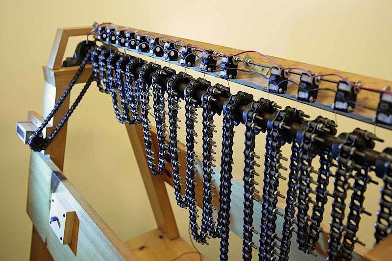
11.1 About This Volume
This is the first of three build volumes. It turns the machine described in Volume 6 — D. H. Lehmer’s frame of bicycle chains, finished as a Berkeley undergraduate in 1926–27 — into a design that can be cut, bought and assembled in a home shop with a 3D printer, a CNC router and a laser cutter. The design is deliberately faithful: real roller chain on real sprockets, one loop per modulus, a mechanical contact over every loop, and a motor that stops when every loop agrees. The modern parts are confined to the places where they make the machine more trustworthy without changing what it is: an encoder on the drive motor that counts the steps, a small microcontroller that latches the count at the instant the contacts agree, and a motor driver that can brake. The contacts themselves are wired the way Lehmer wired his: normally closed, in parallel, breaking to stop.
The volume runs in the order a builder needs it: the brief and the arithmetic that fixes every dimension; the chain, sprockets and shaft; the tabs that mark acceptable residues; the switches and how they are wired; stopping and overrun; the frame; a bill of materials with dated price estimates; the procedure for loading a problem, with the script that computes it; safety; and finally calibration and a first test problem whose answer is known in advance.
None of this has been built yet. Everything here is a design and a procedure. Where the account of the actual build will go, the text carries a marker.
11.2 What the Original Did, in One Paragraph
Lehmer’s own description is short enough to keep beside the bench. In “The Mechanical Combination of Linear Forms” (American Mathematical Monthly 35, 1928, pp. 114–121; copy at cr.yp.to) he lists nineteen chains of 64, 27, 25, 49, 22, 26, 17, 19, 23, 29, 31, 37, 41, 43, 47, 53, 59, 61 and 67 links. “Each chain hangs in a loop from a sprocket having 10 teeth. All the 19 sprockets are fixed rigidly to a single shaft driven by a motor.” Acceptable values are marked by “small pins fastened to the appropriate links of the chain (the zero link being indicated by red paint)”. A pin arriving at the top lifts “a small spring with a tungsten point”, breaking its contact with “a brass bar running parallel to the shaft”; through a relay the motor stops when every spring is lifted at once, and the number is read “directly by means of a revolution counter connected to the shaft. The shaft revolves 300 r.p.m. so that the machine canvasses 3000 numbers per minute.” That is fifty candidates a second. In a later paper Lehmer gave the reason he did not push it harder: “Higher speeds of operation are impractical on account of the instability of the chains and the unreliability of the electrical contacts” (D. H. Lehmer, “A machine for combining sets of linear congruences,” Mathematische Annalen 109, 1934, p. 663; scan at GDZ Göttingen).
Both weaknesses he named — chain stability and contact reliability — are exactly where this design spends its effort.
11.3 The Design Brief
The reproduction has to do six things.
- Count. One step of the shaft must advance every chain by exactly one link, and the step count must be known without ambiguity.
- Remember a residue. A loop of m links must present link k at the top on every step x with x ≡ k (mod m). This is the whole of the arithmetic, and it is done by the chain’s length.
- Mark acceptable residues. Each link must be able to carry, or not carry, a tab that a switch can feel — and the tabs must be movable, because every problem needs a different set.
- Combine. The machine must detect the steps on which every chain presents a tab at once.
- Stop and report. It must stop on such a step, or at least record it exactly, even though a motor running at speed cannot stop instantly.
- Survive long runs. Lehmer’s 9,999,000,099,990,001 run lasted about two hours; a run at a gentler speed lasts much longer. Nothing may drift.
Two questions shape everything else: how many chains, and what chain.
11.3.1 How many chains: eight first, nineteen later
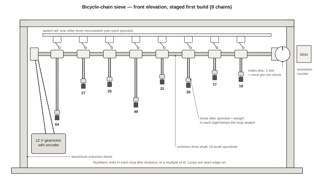
The first build has eight chains — 64, 27, 25, 49, 22, 26, 17 and 19 links, the first eight of Lehmer’s list. That is the machine this volume designs: its bill of materials, frame, loading procedure and test problem are all for eight. The eight exercise every mechanical problem the full machine has: the long 64-link loop, the prime-power loops (27, 25, 49), the doubled short primes (22 for 11, 26 for 13), and the two shortest loops that tension hardest. They need 249 links of chain, eight sprockets, eight switches and a shaft about half a metre long.
All nineteen — Lehmer’s full set, which can rerun every problem in his 1928 paper (Volume 14) — is the later expansion. It needs 740 links, nineteen sprockets, nineteen switches and a frame more than a metre long. Everything in the eight-chain build is sized so the remaining eleven chains (23, 29, 31, 37, 41, 43, 47, 53, 59, 61 and 67 links) drop onto a longer shaft and the same switch bus later; where the expansion changes a number, the text and the bill of materials give it alongside.
What the eight-chain machine cannot do is reject as hard. On Lehmer’s problems its eight loops pass roughly one candidate in a hundred to a few hundred, where his nineteen pass one in 200,000 to 650,000. On the factor of 3¹¹¹ + 1 that difference does not matter — the answer comes at step 145, and the eight-chain machine reaches it with no false stop on the way (Volume 14 computes this exactly). On 9,999,000,099,990,001 it matters enormously: eight chains stop 3,568 times on non-answers before the answer, which is why the controller described below checks every stop automatically and keeps going.
11.3.2 Why the loop length is the modulus
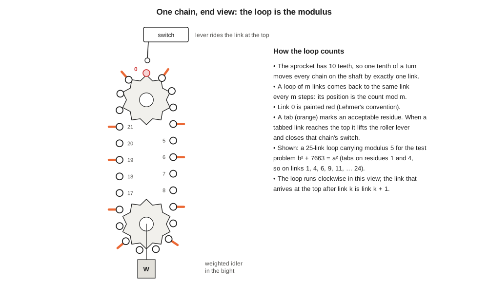
A sprocket with ten teeth advances its chain by one pitch every tenth of a revolution. Every sprocket on the shaft has the same ten teeth, so every chain advances one link per tenth of a turn, whatever its length. After x steps a loop of m links has moved x links, which is the same as having moved x mod m links: link number (x mod m) is at the top. No gear ratio is involved and none can be wrong; the modulus is simply the number of links in the loop. That is why the build can mix lengths freely, and why a loop of 22 links can stand in for modulus 11 — it presents residue r at links r and r + 11, so it carries the mod-11 pattern twice.
The same arithmetic makes the revolution counter decimal: ten steps per revolution means the counter’s reading is the candidate number divided by ten, and the sprocket’s position within the turn is the last digit. Whether Lehmer chose ten teeth for that reason is not recorded; the effect is the same.
11.3.3 Why short loops are doubled
Lehmer’s chains for 11 and 13 have 22 and 26 links. His paper says only that the lengths are “a convenient multiple of some small prime.” The mechanical reason is easy to see: a ten-tooth sprocket wraps about five links over its top half, so an 11-link loop would leave six links hanging in a bight barely deeper than the sprocket itself — too little weight to keep the chain seated and too little room for a tensioner. kbsriram gives the same reading in his notes (“11- and 13-link chains were too short to hang under tension on the sprockets,” code/06/rpi/slower/prob_f111.py in github.com/kbsriram/a-tiny-sieve). The reproduction follows Lehmer: 22 and 26.
11.4 Chain and Sprockets
11.4.1 Choosing the chain
Lehmer’s chains were ordinary bicycle chains (D. N. Lehmer, “Hunting Big Game in the Theory of Numbers,” Scripta Mathematica 1, 1932; transcription). Modern bicycle chain is ½ in (12.7 mm) pitch. Three chains are reasonable candidates:
Table 1 — Lehmer's chains were ordinary bicycle chains (D. N. Lehmer, "Hunting Big Game in the Theory of Numbers," Scripta Mathematica 1, 1932; [transcription](https://ed-thelen.org/comp-hist/Lehmer-NS03.html)). Modern bicycle chain is ½ in (12.7 mm) pitch. Three chains are reasonable candidates
| Chain | Pitch | 67-link loop | 10-tooth sprocket | Notes |
|---|---|---|---|---|
| Bicycle, ½ × ⅛ in (single-speed) | 12.7 mm | 851 mm | not stocked for shaft mounting; cut from plate | most faithful; master links and half-links common |
| ANSI #35 | 9.525 mm (⅜ in) | 638 mm | stocked: Martin 35BS10 | bushing chain (no rollers); attachment and offset links stocked |
| ANSI #25 | 6.35 mm (¼ in) | 425 mm | stocked | very light; tabs fiddly; switch spacing tight |
The chain for this build is ANSI #35, on Martin 35BS10 ten-tooth sprockets. Lehmer used bicycle chain, and bicycle chain would be the most faithful choice; #35 is chosen for two practical reasons. Sixteen of the nineteen loops — five of the first eight — have an odd number of links and need an offset link each, and #35 offset links are stocked catalogue items, as are attachment links. And ten-tooth #35 sprockets are stock parts with a finished, keyed bore, where ten-tooth sprockets for bicycle chain would have to be cut from plate. The Martin 35BS10 is a ten-tooth, finished-bore #35 sprocket with a 1.214 in pitch diameter and 1.379 in outside diameter, offered bored for ⅜, ½ and ⅝ in shafts with a keyway and set screws (distributor listings, e.g. Source Atlantic, 35BS10 ⅜ in bore). A useful detail in Martin’s stock-bore convention is that the keyway is cut on the centreline of a tooth: every sprocket keyed to one keyed shaft — eight now, nineteen later — is therefore in tooth phase with the others, and every chain’s link arrives at the top at the same instant. That is the mechanical equivalent of a common clock edge.
The bicycle-chain option remains open for anyone who wants Lehmer’s actual chain. Ten-tooth sprockets for ½ × ⅛ in chain can be cut on the CNC router from ⅛ in (3 mm) aluminium or steel plate, using a standard ANSI tooth form for ½ in pitch; bicycle sprocket teeth are about 2.8–3.0 mm thick for ⅛ in chain. The pitch diameter of a ten-tooth ½ in sprocket is 0.5 / sin 18° = 1.618 in (41.1 mm). The frame, switches and controller in the rest of this volume do not change, only the spacing along the shaft.
11.4.2 Odd lengths need offset links
Ordinary roller chain alternates inner and outer links, so a closed loop wants an even number of pitches. Sixteen of Lehmer’s nineteen lengths are odd (all but 64, 22 and 26). Each odd loop therefore needs one offset link (a “half link” in bicycle terms), which is a single cranked link that joins an inner end to an inner end. Offset links are standard catalogue items for #35 and #40 chain and for single-speed bicycle chain. Fit the offset link as link 0 — the red link — so it is easy to find and so the one non-standard link is always the reference.
11.4.3 Lengths and how they hang
The free loop below each sprocket is the chain length less the five links wrapped over the sprocket and the five wrapped round the idler, split between two strands. For #35 chain:
Table 2 — The free loop below each sprocket is the chain length less the five links wrapped over the sprocket and the five wrapped round the idler, split between two strands. For #35 chain
| Links | Modulus | Loop length | Each strand (sprocket to idler) | Tensioning |
|---|---|---|---|---|
| 64 | 2⁶ | 610 mm | 27 links, 257 mm | 10-tooth idler + weight |
| 27 | 3³ | 257 mm | 8.5 links, 81 mm | 10-tooth idler + weight |
| 25 | 5² | 238 mm | 7.5 links, 71 mm | 10-tooth idler + weight |
| 49 | 7² | 467 mm | 19.5 links, 186 mm | 10-tooth idler + weight |
| 22 | 2 × 11 | 210 mm | 6 links, 57 mm | small idler + weight |
| 26 | 2 × 13 | 248 mm | 8 links, 76 mm | 10-tooth idler + weight |
| 17 | 17 | 162 mm | 3.5 links, 33 mm | small idler (6–8 teeth) + weight |
| 19 | 19 | 181 mm | 4.5 links, 43 mm | small idler (6–8 teeth) + weight |
| 23 … 67 | primes | 219–638 mm | 6.5–28.5 links | 10-tooth idler + weight |
The eight chains of the first build take 249 links, 2.4 m (7.8 ft) of #35 — one 10 ft box. The full nineteen total 740 links: about 7.05 m (23.1 ft), or three 10 ft boxes with spare.
A ten-tooth idler (outside diameter 1.379 in) cannot sit in the 17- and 19-link loops: the strands are shorter than the sum of the two sprocket radii. Those two loops get a small idler — a 3D-printed six- or eight-tooth #35 wheel with a steel slug pressed into it as the weight.
11.4.4 Tension: the weighted idler
Lehmer’s chains simply hung. At his 300 rpm a hanging bight whips, and even at this build’s speeds a short loop can lift, and a whipping chain can climb a tooth and slip a link — after which every answer is wrong and nothing announces it. The reproduction puts a loose idler sprocket in the bight of every loop, free to rotate on a short axle, with a weight hung from the axle. The idler keeps the chain seated on the drive sprocket with a known, constant tension, damps the bight, and makes the loop length irrelevant to tension. A weight of 100–200 g per loop is a sensible starting point for #35; adjust until the chain does not lift off the sprocket at the demonstration speed (below). The idler axle must not be fixed to the frame: a fixed idler would have to be repositioned for every chain length and would fight the chain’s stretch. Hang it.
A light vertical guide — two strips of UHMW or printed PETG either side of each idler — keeps the weights from swinging into each other without taking their weight.
11.4.5 Shaft, bearings and drive
The shaft is ⅝ in keyed steel (precision ground, with a 3/16 in keyway to suit the 35BS10’s ⅝ in bore option), carried in two pillow-block bearings at the ends (the nineteen-chain expansion adds a third in the middle). Sprocket spacing along the shaft is set by the switches, not the chain: allow 50 mm between sprocket centres for an Omron SS-size switch with its lever, which makes the eight-chain shaft about 500 mm between outer sprockets, and the nineteen-chain shaft about 1,000 mm.
The motor is a 12 V DC gearmotor with an encoder: the Pololu “50:1 Metal Gearmotor 37Dx70L mm 12V with 64 CPR Encoder (Helical Pinion)”, item #4753 (product page). Pololu gives it about 200 rpm at no load at 12 V, 200 mA free-running and 5.5 A at stall (an extrapolated figure), with a recommended continuous load of up to 10 kg·cm. Its encoder gives 64 counts per motor revolution, counting both edges of both quadrature channels, which is 3,200 counts per revolution of the 6 mm output shaft.
The motor drives the ⅝ in shaft 1:1 through a timing belt (GT2 or HTD pulleys, one bored 6 mm D for the motor and one ⅝ in for the shaft), which isolates the motor’s vibration while keeping the encoder locked to the sprockets. With ten teeth on every sprocket, one shaft revolution is ten steps, so the encoder gives 320 counts per step — enough to place a read window inside a step with precision to spare. Speeds follow directly:
- rated running speed, 10 steps/s — 60 rpm at the shaft, the motor on PWM at well under half its no-load speed; and
- demonstration ceiling, about 30 steps/s — 180 rpm, close to the motor’s 200 rpm no-load limit.
Lehmer’s own 300 rpm (50 steps/s) is beyond this drive at 1:1. That is no great loss: the switches’ operating-rate limits (below) say much the same thing, since the busiest chains are already outside the SS series’ datasheet rating well before 50 steps a second. A NEMA 23 stepper with a microstepping driver is a workable alternative drive; the rest of the design does not change.
The other end of the shaft carries a single-slot index disc and, if wanted, a mechanical revolution counter. The index is not needed to count — the motor encoder does that — but it earns its place twice: it homes the machine (the step phase is set from it at power-up), and it checks the belt once per revolution, since the controller must see exactly 3,200 encoder counts between index pulses. A belt that skips a tooth would otherwise shift every chain’s phase silently.
11.5 Tabs: Marking the Acceptable Residues
11.5.1 What a tab must do
Lehmer marked acceptable residues with small pins — in Lukes’s account “a piece of chicken wire, actually” (R. F. Lukes, A Very Fast Electronic Number Sieve, PhD thesis, University of Manitoba, 1995, p. 14). A pin on the link at the top of the sprocket lifted the spring above it. The 1981 reproduction replaced chosen pivot pins with screws with long tails that trip microswitches (Computer History Museum, catalog 102647620). Both are fine. A tab for the reproduction has to:
- present a feature that rises clear of the chain by enough to move a switch lever through its full travel, but only when its link is at the top;
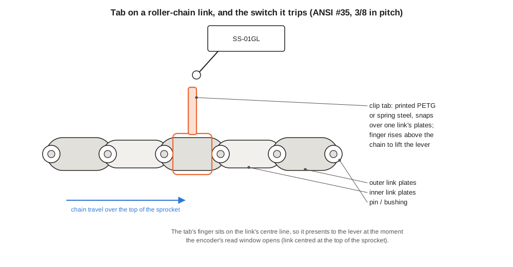
- sit on the centreline of its link, so it presents at the same shaft angle as the controller’s read window;
- go on and come off by hand, in seconds, without breaking the chain;
- survive the trip round the sprocket and idler at the demonstration speed without loosening;
- be impossible to fit to the wrong link by accident.
11.5.2 The clip tab
The default tab is a clip printed in PETG that snaps over the side plates of one link and carries a short upright finger. Two versions are needed, because the inner and outer links of roller chain have different widths over the plates: colour them differently (for example, black for inner links and white for outer links) so the right clip goes on the right link without measuring. The finger stands about 6 mm above the chain’s top edge and is about 4 mm wide in the direction of travel; it should not reach over a neighbouring link, or it will hold the lever up across two steps.
Spring-steel clips are the durable alternative — bent from 0.3–0.4 mm spring steel strip on a simple jig — and are worth making once the printed geometry has been proven.
For a fully faithful machine, the tab can be what Lehmer used: a twist of soft wire round the link, with a short tail standing up. It is slower to fit and harder to make consistent, but it is historically exact, and it is worth fitting at least one problem’s worth that way.
11.5.3 Numbering the links
Paint link 0 red, as Lehmer did, and put the offset link there on the odd chains. Then number from it in the direction the chain travels over the top, so that link k + 1 arrives under the switch one step after link k. A paint pen dot every fifth link (5, 10, 15 …) makes counting quick, and a printed loading strip for each problem (below) does the rest: it is laid along the chain and the tabs are clipped on where the strip says.
The loading strip is also the record of a run. Keep it with the run log; it says exactly which residues every chain accepted.
11.6 The Switches
11.6.1 Choosing a microswitch
The switch over each sprocket has one job: open its normally closed contact reliably when a finger lifts its lever, and close it again when the finger passes, many millions of times, at a logic-level current. Three Omron families cover the range, and their datasheets settle the choice:
Table 3 — The switch over each sprocket has one job: open its normally closed contact reliably when a finger lifts its lever, and close it again when the finger passes, many millions of times, at a logic-level current. Three Omron families cover the range, and their datasheets settle the choice
| Switch | Lever | Contacts | Minimum load | Mechanical rate limit | Mechanical life |
|---|---|---|---|---|---|
| Omron SS-01GL | hinge roller | gold alloy | 1 mA at 5 VDC | 400 operations/min | 10–30 million (by model) |
| Omron V-156-1C25 | short hinge roller | silver | 160 mA at 5 VDC | 600 operations/min | 50 million |
| Omron D2F-01L2 | hinge roller | gold alloy | 1 mA at 5 VDC | 100 operations/min (lever) | 1 million |
(Omron datasheets: SS, V, D2F.)
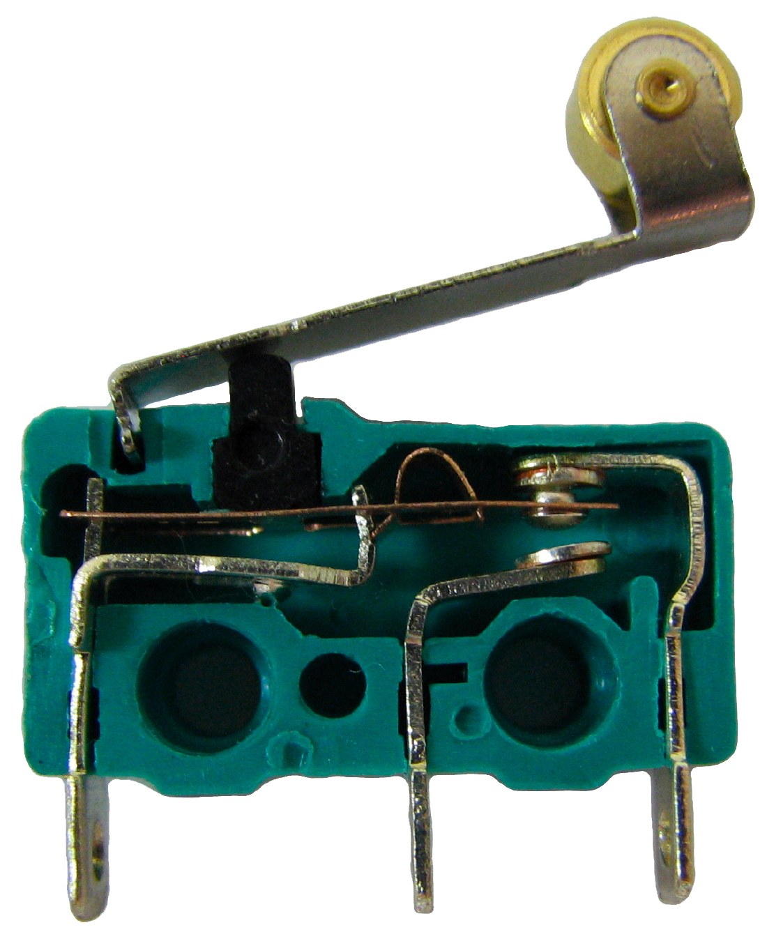
The SS-01GL is the choice. It is a changeover switch (common, normally closed and normally open terminals), so the same part serves either polarity; this build uses its normally closed terminals. The minimum-load row is the decisive one: a bus of switches read by a microcontroller carries a milliamp or two, and silver contacts specified for 160 mA minimum will grow a film and start to fail at that current. The V series is the right choice only for the faithful relay version, where the contacts carry a relay coil’s current directly. The D2F is too short-lived for this duty.
The mechanical rate limit matters more than it first appears. A switch operates once for every run of consecutive tabbed links that passes it, not once per tab. For Lehmer’s problems the busiest chain sees a fresh run on 35–43 per cent of steps (computed from the tab patterns by chain_tabs.py). At Lehmer’s fifty steps a second that is 1,060–1,290 operations a minute — two to three times the SS rating and about twice the V rating. At ten steps a second (60 rpm at the shaft) it is 210–260 a minute, comfortably inside the SS rating. At the drive’s demonstration ceiling of about 30 steps a second it is 630–770 a minute: roughly twice the SS rating, about the V rating. So the motor’s limit and the switches’ limit land in the same place, and the reproduction has two speeds:
- rated speed, 10 steps/s, for long unattended runs; and
- demonstration speed, up to about 30 steps/s, for short runs, accepting that the busiest switches are being worked beyond their datasheet’s mechanical rate.
Lehmer’s own springs were working at his machine’s limit too: he named “the unreliability of the electrical contacts” as the reason it could not go faster.
11.6.2 Mounting
Each switch is screwed to a small printed bracket on the switch rail — a length of 20 × 20 mm extrusion parallel to the shaft and above it. The bracket is slotted so the switch can be raised and lowered: set it so that the roller just clears an untabbed link at the top of the sprocket with about 1 mm to spare, and so that a tab’s finger drives the lever past its operating point by another 1–2 mm (the datasheet’s overtravel). The roller should meet the finger on the sprocket’s top centreline. Lehmer’s tungsten-pointed spring sat in the same place for the same reason.
Hinge the whole switch rail at one end, as the 1981 reproduction did with its flip-up switch frame, so the rail can be swung clear for loading tabs.
11.6.3 Series or parallel: Lehmer’s break-to-stop
Lehmer’s 1928 description and the later accounts disagree on the polarity of the contacts. In his own words, each pin lifts a spring off a common brass bar and breaks its contact, and the machine stops only when every spring is lifted at once. Electrically, that is normally closed contacts in parallel: current flows while any spring touches the bar, and the circuit opens when all of them are lifted. Lukes describes the contacts as “connected in series,” with “completion of the circuit” tripping the relay, and the 1981 reproduction uses microswitches that close. The two are logically the same — both detect “every chain accepts” — but they fail differently, and the difference decides the design:
- Make-to-stop in series (normally open contacts, all must close). A broken wire, a dirty contact or a switch set too high means the string can never close. The machine then runs past every answer and reports nothing. This is a silent failure, and it loses answers.
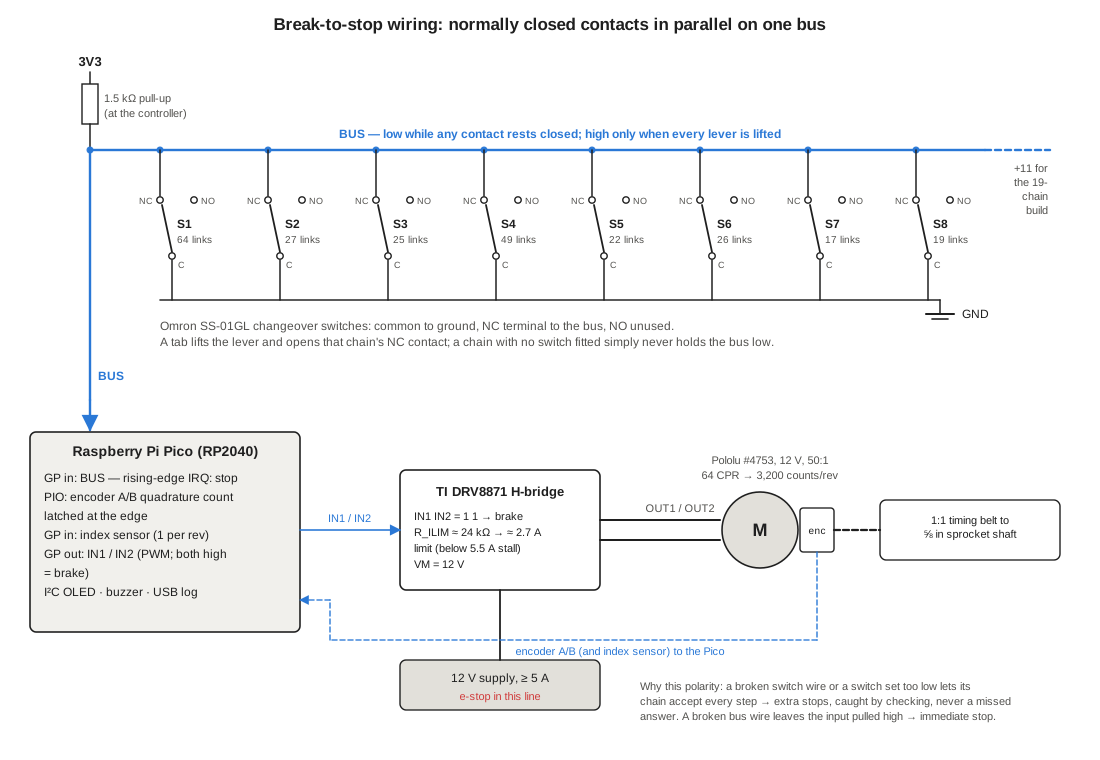
- Break-to-stop in parallel (Lehmer’s springs, normally closed contacts). A broken wire to a switch, or a switch set too low, leaves that chain’s contact permanently open: the chain accepts every step, and the machine stops more often than it should. Each extra stop is a false stop, which the controller’s checking catches; no answer is ever passed over. A broken wire between the bus and the controller reads as “every chain accepts”, and the machine stops at once.
This build therefore uses Lehmer’s own arrangement: break-to-stop, normally closed contacts in parallel. The commonest faults — a wire broken by vibration, a connector worked loose, a switch knocked out of adjustment — all fail in the useful direction, towards extra stops that are caught by checking, never towards a silently missed solution. It is also how Lehmer described his machine, and it gives a faithful way to take a chain out of a problem: a chain with no switch connected simply never holds the bus, just as Lehmer’s chains without springs took no part (“When several chains are provided with springs …”, LF28 p. 115).
One failure remains that this polarity cannot make noisy: a contact that never opens — a welded contact, a broken lever, or a switch mounted so high that a tab does not lift it far enough. That chain then rejects every step and suppresses every stop. It is the same silent failure as the series string’s, reached by fewer routes, and the all-accept bus test before every run (under “Calibration”) is designed to catch exactly it.
11.6.4 Wiring
Each SS-01GL is wired with its common terminal to ground and its normally closed (NC) terminal to a single bus; the normally open terminal is left unconnected. All eight switches — nineteen after the expansion — sit in parallel between the bus and ground. A 1.5 kΩ pull-up to 3.3 V, mounted at the controller end, holds the bus up whenever nothing pulls it down:
- while any chain presents an untabbed link, its lever is down, its NC contact is closed, and the bus is held low;
- when every chain presents a tab at once, every lever is lifted, every NC contact is open, and the pull-up takes the bus high.
The rising edge is the stop signal. It goes to a GPIO on the Pico configured for a rising-edge interrupt.
At 3.3 V and 1.5 kΩ the bus sinks 2.2 mA. The contacts share that current while several are closed, but the one that matters — the last contact still closed before a stop, whose opening the controller must see — carries all 2.2 mA, above the SS-01’s 1 mA minimum load and far below anything that would wear gold contacts.
Putting the pull-up at the controller, not at the switches, is what makes a broken bus wire safe: if the cable from the switch rail is cut or unplugged, the controller’s input is left with only its pull-up, reads high, and stops the machine immediately. Use twisted pair or shielded cable for the run back to the controller and keep it away from the motor leads: a metre of bus with a 1.5 kΩ source impedance is a fine antenna. The gear machine’s builders lost days to a short-wave amateur next door (Volume 7); the chain machine’s slow signal is less vulnerable, and the read window below is the real protection. A 100 nF capacitor from the bus to ground at the controller filters fast spikes without slowing a stop measurably.
Diagnostic option. In a plain parallel bus the controller sees only the combined result. To see which chain is rejecting at any step, give each switch its own wire to a small junction board, with its own pull-up and a Schottky diode (anode to the bus, cathode to the switch line) joining it to the bus; a 74HC165 shift register reads every switch line. The bus logic is unchanged — any closed contact still pulls the bus low through its diode — and the controller can now see, for example, a chain that never accepts (the never-opening contact above) during a run.
11.7 Counting, Reading and Stopping
11.7.1 The read window
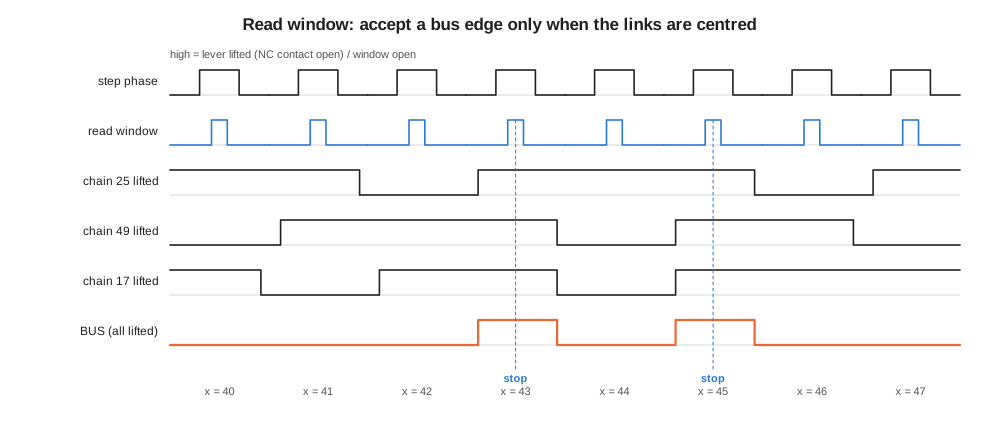
A lever is lifted a little after a finger reaches its roller and drops a little before the finger leaves, and two neighbouring tabs on the same chain may hold a lever up across a step boundary. A bus edge at an arbitrary moment can therefore come from the ragged end of one step and the beginning of the next, and report a coincidence that never happened. The cure is to accept a stop only when every link is centred at the top of its sprocket.
The motor encoder provides that moment. At 320 counts per step, the count modulo 320 is the shaft’s phase within the current step. Calibration (below) finds the phase at which a link is centred at the top, and the controller defines a read window of a few dozen counts around it. A bus edge latched inside the window is a stop on that step; an edge latched outside it is logged as a glitch and ignored. A properly adjusted machine never produces glitches; a stream of them means a switch is out of adjustment.
The index disc ties the phase to the sprockets: a single slot through an Omron EE-SX1041 slot photomicrosensor (datasheet; a general-purpose transmissive sensor with a 5 mm slot) marks one fixed shaft angle per revolution. Because every sprocket is keyed in tooth phase (above), one encoder and one index serve every chain.
11.7.2 The controller
The controller is a Raspberry Pi Pico (RP2040), chosen for the same reason kbsriram chose it for the electronic sieve in Volume 13: its PIO state machines can count encoder edges and latch the count in hardware, with timing that does not depend on the main program (RP2040 datasheet; Pico pinout). One state machine decodes the motor encoder’s two quadrature channels into a signed 32-bit count (more than enough: Lehmer’s longest range, 5.8 million steps, is under 1.9 billion counts). The bus rising edge is wired as an interrupt; the same edge makes the PIO push the count at that instant into a FIFO, so the latched count is exact however long the interrupt takes to be serviced. On each stop the program:
- brakes the motor (both DRV8871 inputs high);
- checks that the latched count’s phase lies in the read window — if not, it logs a glitch and restarts;
- converts the count to a step number and the step to the candidate, using the problem’s linear form and start value;
- tests the candidate — is the quadratic a perfect square? — in a few milliseconds;
- if it is an answer, sounds the buzzer and puts the answer on the display, leaving the machine stopped;
- if not, logs it as a false stop and restarts the motor.
This is the architecture of every sieve from the 1960s onward: a fast rejecter and a slower checker. It is what makes the eight-chain machine usable on problems where it stops thousands of times. Braking and restarting costs perhaps half a second a stop; on problems with many false stops the controller can instead test the candidate without braking and brake only on an answer, since the latched count is exact either way.
A faithful mode skips steps 3–6: every coincidence stops the machine, as Lehmer’s relay did, and an operator reads the counter and does the arithmetic by hand. Run the first problem this way.
11.7.3 Stopping, overrun and finding the stop
Lehmer’s 1928 paper says nothing about how far the chain machine coasted after its relay cut the motor. For the faster gear machine he describes the procedure exactly: the operator “substitutes the human eye for the photo-electric cell, and by reversing the machine very slowly, brings it back to the exact position where the light shines through. He then reads the number of teeth by means of a revolution counter” (Math. Annalen 109, 1934, p. 664). At 300 rpm the chain machine’s shaft, sprockets and nineteen loaded chains would also have carried on for some fraction of a revolution after the relay opened — several steps — and the same back-off by hand must have been how the stop was read. (That is an inference; the paper does not say.)
The reproduction makes overrun harmless rather than small. The encoder count is latched in hardware at the bus edge, so it is exact however far the shaft coasts afterwards, and the motor is then stopped as quickly as the drive allows.
The driver is a TI DRV8871 brushed-DC H-bridge (datasheet, SLVSCY9B): 6.5–45 V supply, up to 3.6 A peak, two PWM inputs, and a brake state when both inputs are high (both low-side switches on, shorting the motor). Setting both inputs low lets the motor coast and puts the chip to sleep. It needs no sense resistor: the current limit is set by one resistor on its ILIM pin, ITRIP = 64 kV / RILIM (typical; the datasheet’s example is 32 kΩ for 2 A, and 15 kΩ is the minimum). Set the limit below the motor’s stall current — about 24 kΩ gives roughly 2.7 A, near the motor’s recommended continuous load — so that a jammed chain is held at a safe current rather than stalling the motor at 5.5 A; the chip’s separate overcurrent protection (tripping at 3.7–6.4 A) stays in place as a backstop. Power it from a 12 V supply rated at 5 A or more. At rated speed a braked gearmotor on a lightly loaded shaft should stop within a step or two; how far it actually runs on is something to measure on the first runs, and with the count latched it does not matter.
Two alternatives remain:
- Stepper motor: a NEMA 23 stepper with a microstepping driver can decelerate under control and stop on the step itself.
- Relay (the faithful version): Lehmer’s own arrangement, with the parallel NC contacts carrying a relay coil’s current (V-series switches) so that the relay drops out and cuts the motor when every contact opens, exactly as in 1928. The motor coasts; the operator backs it off by hand.
After any stop, the controller can walk the shaft back slowly under PWM to the latched count and hold it there, so the tabs that caused the stop are all at the top of their sprockets for inspection — the mechanical version of Lehmer’s “reversing the machine very slowly”. Checking the stop by eye on the first runs is the best possible test that the read-window phase, the tabs and the switches all agree.
11.7.4 Counters
Fit a mechanical five- or six-digit revolution counter to the index end of the shaft, driven 1:1. It reads the candidate number divided by ten, exactly as Lehmer’s did, and needs no power. It is a satisfying instrument to read, and it is an independent check on the electronic count: at every stop, ten times the counter plus the sprocket’s position within the turn should equal the latched step.
A 0.96 in SSD1306 OLED on the Pico’s I²C bus shows the step count, rate, stops and the last answer; the same messages go to USB serial for the log.
11.8 The Frame
The frame is aluminium extrusion — 20 × 40 mm or 40 × 40 mm T-slot for the uprights and top beam, 20 × 20 mm for the switch rail and chain guides — on a plywood or extrusion base. T-slot makes every position adjustable, which matters on a first build where the bearing heights, switch heights and idler guides will all be moved more than once.
Overall sizes for the eight-chain #35 build (the nineteen-chain expansion in brackets):
- Width: shaft length plus bearings plus the index disc and counter at one end and the belt pulley at the other: about 750 mm (1,250 mm for nineteen). Building the frame at the expansion width from the start costs little and avoids rebuilding it later.
- Height: the longest loop (64 links; 67 after the expansion) hangs about 300 mm below the shaft centre including its idler and weight; the shaft sits about 120 mm below the top beam to leave room for the switch rail. A 600 mm frame height leaves clearance under the weights.
- Depth: a 300 mm base footprint with diagonal braces at the ends keeps it stable; the machine’s mass is low and it runs smoothly when the shaft is true.
The motor sits on the base under one end of the shaft, belted up to the shaft pulley. Mount the pillow blocks on adjustable plates so the shaft can be trued: a shaft that runs out of true by a fraction of a millimetre at the sprockets moves the tabs relative to the switch rollers once per revolution.
The CNC router cuts the bearing plates, switch brackets (in aluminium, if not printed) and the index disc (from 1.5 mm aluminium: one slot 3 mm wide on a 30 mm radius). The laser cuts the chain guides and the loading-strip templates. The printer makes tabs, idlers for the short loops, switch brackets and cable clips.
11.9 Bill of Materials
Prices are estimates in US dollars, gathered October 2026 from distributor listings, for orientation only; they will vary by supplier and over time. The first build is eight chains; the nineteen-chain columns are the later expansion.
Table 4 — Bill of Materials
| Item | Specification | Qty (8, first build) | Qty (19, expansion) | Est. unit price | Est. total (8) | Est. total (19) |
|---|---|---|---|---|---|---|
| Roller chain | ANSI #35, riveted, 10 ft box | 1 | 3 | $25 | $25 | $75 |
| Offset links | ANSI #35 | 5 | 16 | $3 | $15 | $48 |
| Connecting (master) links | ANSI #35 | 8 | 19 | $1 | $8 | $19 |
| Drive sprockets | Martin 35BS10, ⅝ in bore, keyed | 8 | 19 | $25 | $200 | $475 |
| Idler sprockets | #35 10-tooth, plain bore (or printed) | 6 | 17 | $12 | $72 | $204 |
| Small idlers | printed 6–8-tooth #35, steel slug | 2 | 2 | $1 | $2 | $2 |
| Idler weights | steel, 100–200 g | 8 | 19 | $2 | $16 | $38 |
| Shaft | ⅝ in keyed precision steel, 36 in / 48 in | 1 | 1 | $35 / $45 | $35 | $45 |
| Key stock | 3/16 in square | 1 | 1 | $5 | $5 | $5 |
| Pillow-block bearings | ⅝ in bore (UCP202-10 class) | 2 | 3 | $12 | $24 | $36 |
| Microswitches | Omron SS-01GL (gold, roller lever) | 8 | 19 | $5 | $40 | $95 |
| Diagnostic option | 74HC165 shift registers + Schottky diodes | 1 + 8 | 3 + 19 | — | $2 | $4 |
| Controller | Raspberry Pi Pico (RP2040) | 1 | 1 | $5 | $5 | $5 |
| Index sensor | Omron EE-SX1041 + one-slot disc | 1 | 1 | $5 | $5 | $5 |
| Display | 0.96 in SSD1306 I²C OLED | 1 | 1 | $8 | $8 | $8 |
| Motor | Pololu #4753: 50:1 37D 12 V gearmotor, 64 CPR encoder | 1 | 1 | $61 | $61 | $61 |
| Motor driver | TI DRV8871 breakout board, RILIM ≈ 24 kΩ | 1 | 1 | $8 | $8 | $8 |
| Power supply | 12 V, ≥5 A, enclosed | 1 | 1 | $20 | $20 | $20 |
| Belt drive | GT2/HTD pulleys (6 mm D and ⅝ in bores) and belt, 1:1 | 1 set | 1 set | $20 | $20 | $20 |
| Revolution counter | 5–6 digit mechanical | 1 | 1 | $20 | $20 | $20 |
| Frame | T-slot extrusion, brackets, T-nuts | 1 lot | 1 lot | — | $120 | $180 |
| Chain guards | 3 mm clear polycarbonate | 1 lot | 1 lot | — | $40 | $70 |
| Sundries | wire, connectors, buzzer, e-stop, fasteners, PETG | 1 lot | 1 lot | — | $50 | $70 |
| Total (estimate) | ≈ $800 | ≈ $1,500 |
The motor price is Pololu’s list price for one (US$60.95, October 2026); the DRV8871 board and supply are typical distributor prices. The sprockets are the largest single cost. Cutting them on the CNC router from plate (for bicycle chain or #35) removes most of it at the price of a day’s machining and some care with the tooth form.
11.10 Loading a Problem
11.10.1 From problem to tab pattern
Every problem the machine can run reduces to the same form: find whole numbers x in a range for which a quadratic Q(x) = c₂x² + c₁x + c₀ is a perfect square. Volume 9 shows how factoring by a difference of squares, representation as a sum of two squares and the pseudosquare problem all take this form; Volume 4 explains why the test works. For each chain of modulus m, the acceptable residues are the values x mod m for which Q(x) is a square modulo m (zero included). A link k of a chain with L links gets a tab when k mod m is acceptable.
Two refinements from Lehmer’s paper are worth keeping:
- Moduli that share a factor with the step. When the linear form already fixes x modulo part of a modulus (the factor of 3¹¹¹ + 1 has a step of 49,284 = 2² · 3² · 37², which shares factors with 27 and 37), the plain square test admits too much. Lehmer worked the 27-link chain modulo 9 instead (x ≡ 1, 4, 7, 8 mod 9) and reduced the form for 37. The script carries these as overrides.
- Shifting the origin instead of moving tabs. For his second sum-of-two-squares run (a = 5x + 3 instead of 5x + 2) Lehmer did not move a single pin: “instead of setting all the chains on their zero positions we set them on the link corresponding to the value of 1/5 (mod p)” (LF28 p. 120). A chain’s starting link is part of the problem.
11.10.2 The script: chain_tabs.py
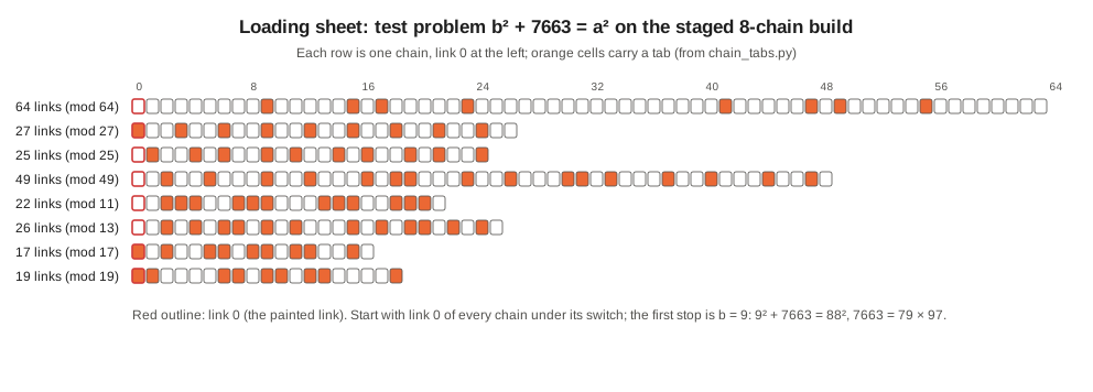
The loading sheet is computed by 03-outputs/cad/chain_tabs.py (Python 3, standard library only). It holds presets for the test problem and for Lehmer’s four 1928 runs, prints the tabbed links for every chain, predicts the number of chance stops, simulates the machine over ranges short enough to walk, and checks itself against Lehmer’s published answers. Its core is a dozen lines:
def squares_mod(m):
    """Set of quadratic residues modulo m, 0 included."""
    return {(r * r) % m for r in range(m)}


def allowed_residues(coeffs, m):
    """Residues x mod m for which Q(x) is a square modulo m."""
    c2, c1, c0 = coeffs
    sq = squares_mod(m)
    return [x for x in range(m) if (c2 * x * x + c1 * x + c0) % m in sq]


def tabbed_links(chain_links, modulus, allowed):
    """Links (0 = the red zero link) that carry a tab on a chain of chain_links."""
    allowed = set(allowed)
    return [k for k in range(chain_links) if k % modulus in allowed]


def start_link(start_x, chain_links):
    """Link that must be under the switch when the counter reads start_x."""
    return start_x % chain_links
Run it with no arguments to print every preset and the self-checks, or with a preset name:
python3 chain_tabs.py test7663_8For the test problem on the eight-chain machine it prints (abridged):
test7663_8 — Same test problem on the staged 8-chain build
Q(x) = 1 x^2 + 0 x + 7663   range x = 0 .. 3831
links  mod  tabs   pass  tabbed links (0 = red zero link)
   64   64     8  0.125  9 15 17 23 41 47 49 55
   27   27     9  0.333  0 3 6 9 12 15 18 21 24
   25   25    10  0.400  1 4 6 9 11 14 16 19 21 24
   49   49    16  0.327  2 5 9 12 16 18 19 23 26 30 31 33 37 40 44 47
   22   11    12  0.545  2 3 4 7 8 9 13 14 15 18 19 20
   26   13    12  0.462  2 4 6 7 9 11 15 17 19 20 22 24
   17   17     9  0.529  0 2 5 6 8 9 11 12 15
   19   19     9  0.474  0 1 6 7 9 10 12 13 18
Chains pass 1 candidate in 2911; predicted chance stops over the range: 1.32
Simulated stops (2):
   x = 9         b = 9, a = 88: N = 79 x 97
   x = 3831      b = 3831, a = 3832: N = 1 x 7663
Self-checks: PASS
The self-checks confirm that every published stop in Lehmer’s 1928 paper — x = 400,453 for 9,999,000,099,990,001, x = 145 for the factor of 3¹¹¹ + 1, x = 196,113 and x = 157,044 for the two sum-of-squares runs — passes every chain, and that the script recovers the published factors. It also reproduces the stops kbsriram found that the paper does not list: the second sum-of-squares run stops at x = 102,151 before the answer, exactly as his ATtiny board did (Volume 14).
11.10.3 The loading procedure
- Run the script for the problem and print the loading sheet. Print each chain’s row at 1:1 scale as a strip (link pitch 9.525 mm for #35) with the tabbed links marked.
- Stop and lock out the machine. Switch off the motor supply and fit the lockout (see Safety).
- Swing the switch rail up on its hinge.
- Remove last problem’s tabs, chain by chain. Count them back into the tray: a tab left behind is a chain that accepts a residue it should reject, which only costs extra stops; a tab missing is a chain that rejects an answer, which loses the answer silently — the one error the break-to-stop wiring cannot catch, because it is in the problem, not the machine.
- Clip on the new tabs chain by chain, laying the strip along the chain from the red link in the direction of travel. Inner-link clips on inner links, outer on outer.
- Set the start links. Turn each chain on its sprocket (with the shaft locked) until the start link from the sheet is at the top. For a run starting at x = 0 that is the red link on every chain; for a shifted origin it is a different link on each. A chain is moved round its sprocket by lifting the idler weight and walking the chain a tooth at a time.
- Check the count. For each chain, count the tabs on the chain against the sheet’s “tabs” column.
- Lower the switch rail, remove the lockout, home the shaft to its index, zero the counters, and enter the problem on the controller (the Pico reads the same preset name).
- Run the start-of-run check (next section) before the motor is allowed to run free.
Lehmer’s gear machine needed over two hours to load a full problem (Lukes 1995, p. 15, citing Stephens 1989). For the eight-chain build with clip tabs, half an hour is a realistic target; after the expansion to nineteen, an hour.
11.11 Safety
A chain sieve is a row of chain-and-sprocket nips running unattended for hours. Treat it as machinery.
- Pinch points. Every chain enters its sprocket and its idler at a nip that will take a fingertip or a loose sleeve. Guard all of them: a clear polycarbonate front and top guard over the sprockets and switch rail, and clear side panels around the loops, with the idler weights inside the guard. Clear guards let the machine be watched, which is half the pleasure of it.
- Interlock the guard. A switch on the front guard in series with the motor enable, so opening the guard stops the drive. The switch rail’s hinge should also open an interlock.
- Emergency stop. A latching mushroom-head e-stop in the 12 V motor supply, cutting it directly, not through the controller.
- Lockout for loading. Loading tabs means hands among the chains with the guards open. Disconnect the motor supply (a keyed switch or a removable plug) before opening the guards, and lock the shaft against rotation with a pin through the index disc.
- Thrown parts. A tab that comes off at the demonstration speed leaves the sprocket at about a metre a second. Run with the guards closed, and count tabs back after every run.
- Unattended running. Lehmer’s machine ran “without any attention” for hours. A home machine running overnight should have its motor supply fused, its motor’s temperature within its rating at the chosen duty, the driver’s current limit set below stall, and the controller set to stop and alarm on any encoder fault (anything other than 3,200 counts between index pulses).
11.12 Calibration and the First Test Problem
11.12.1 Mechanical checks, chain by chain
- Seating. With the motor at rated speed (10 steps/s), watch each loop with a strobe or a phone’s slow-motion video. The chain should not lift off its sprocket at the top or rise on its idler. If it does, add weight to that idler.
- Switch adjustment. With the shaft turned by hand to put an untabbed link at the top, every switch’s NC contact should be closed (continuity meter across common and NC, or the diagnostic option). Turn to put a tabbed link at the top: that switch’s NC contact should open, with overtravel to spare. A switch set too low opens on untabbed links (extra stops); a switch set too high never opens (no stops at all) — the second is the one to fear.
- Read-window phase. Turn the shaft slowly with a tab under each switch in turn and log the encoder count at which each NC contact opens and closes again. The window must lie inside every switch’s open interval with margin on both sides; set the controller’s window centre (a count offset from the index) to the middle of the common interval. Nothing on the shaft needs to be moved — the phase is a number in the controller.
- Count per revolution. Run 100 revolutions; the controller must count 320,000 encoder counts and 100 index pulses (3,200 between each pair), and the mechanical counter must have advanced by 100.
11.12.2 The bus test
Two tests, run before every recorded run and after any disturbance to the switch rail:
- All-accept. Load a tab on every link of every chain and run slowly. The bus must go high on every step and the machine must stop on every step. A chain whose contact never opens — welded, broken lever, switch set too high — holds the bus low and the machine never stops: this test is how the one silent failure of the break-to-stop wiring is caught before a real run depends on it.
- One chain rejecting. Take all the tabs off one chain, leaving every other chain fully tabbed: the machine must never stop. Repeat with each chain in turn. A chain that lets the machine stop here has a broken wire or a switch set too low — a fault that would only have cost extra stops, but one worth fixing.
Together they prove that every switch both holds the bus low and lets it go. During a real run in checking mode, the controller also compares the stop rate with the rate chain_tabs.py predicts for the problem: far fewer stops than predicted is a reason to stop and repeat the all-accept test.
11.12.3 Test problem: 7663 = 79 × 97
The first real problem is the one kbsriram uses to explain sieving on his project page: factor 7663 by finding b with b² + 7663 a perfect square. Modulo 5, 7663 ≡ 3, and b² + 3 is a square mod 5 only when b ≡ 1 or 4 (mod 5). Modulo 7, b ≡ 0, 1 and 6 are excluded. The first b that both moduli allow is 4 — not a solution — and the next is 9, where 9² + 7663 = 7744 = 88², so 7663 = (88 − 9)(88 + 9) = 79 × 97.
Run it in two stages:
- Two chains, faithful mode. Fit only the 25-link chain (for modulus 5: tabs on links 1, 4, 6, 9, 11, 14, 16, 19, 21, 24) and the 49-link chain (for modulus 7: tabs on links 2, 3, 4, 5, 9, 10, 11, 12, 16 …, every link whose number is 2, 3, 4 or 5 mod 7) — and disconnect the other six switches from the bus (or swing them clear), exactly as Lehmer ran chains without springs. A chain with no switch connected never holds the bus low, so it takes no part. Start both chains on their red links with the counter at zero. The machine must stop at x = 4 (a false stop: 4² + 7663 = 7679 is not a square), and on restart at x = 9. Read the counter, back the shaft off to the stop, confirm that both tabs are under their switches, and do the arithmetic by hand.
- All eight chains, checking mode. Reconnect every switch and load the full sheet above. The machine must stop once, at x = 9, and then — if run to the end of the range — at x = 3,831, which is the trivial factorisation 7663 = 1 × 7663 (b = (7663 − 1)/2). Nothing else.
If both stages give exactly these stops, the counting, the tabs, the switches, the read window and the checker all agree. The machine is then ready for Lehmer’s own problems; the eight-chain build’s first real one should be the factor of 3¹¹¹ + 1, which Lehmer’s machine found “after running only 4 seconds” at x = 145 (Volume 14 has the full protocol).
11.13 What the Build Teaches
The chain sieve is the clearest machine in the series because nothing in it is hidden. The modulus is a length that can be counted with a finger; the arithmetic is a coincidence of tabs that can be seen; the answer is a number on a counter. Building it also shows why Lehmer moved on. At fifty steps a second the chains want to whip and the contacts want to bounce, and the switches’ own datasheets say the same thing in operations per minute. Every improvement in this design — weighted idlers, a read window, gold contacts, a hardware-latched count — is a response to one of the two problems he named in 1934, and the one thing kept exactly as he had it, break-to-stop contacts in parallel, turns out to be the safest way to wire them. The next volume builds the machine he built to get past them, where the chains become gears and the contacts become a beam of light.
Next — Volume 12: Building the Photoelectric Gear Sieve. Thirty gears with a hole under every tooth, a light beam along their common line of tangency, a photodiode and comparator to stop the drive, and the alignment that makes it all work.
Comments (0)