Number Sieves · Volume 12
Number Sieves — Volume 12 — Building the Photoelectric Gear Sieve
Thirty gears, one hole under every tooth, a beam of light and a photodiode: a reproduction of Lehmer's 1932 machine designed for a home shop
12.1 About This Volume
In 1932 D. H. Lehmer replaced the chains of his first sieve with thirty gears and its contacts with a beam of light. The machine ran a hundred times faster — five thousand candidates a second — and in its first weeks factored numbers that had resisted every computer of the day (Volume 7). This volume designs a reproduction of it for a shop with a 3D printer, a CNC router and a laser cutter: the gear set and its tooth counts, the holes and plugs, the arrangement that lets one beam pass through every gear, the optics and detector, the controller, the bill of materials, a script that draws every gear, and the procedures for assembling, aligning and testing it.
The design follows Lehmer’s own description wherever one exists, and says so where it has to guess. As with the chain sieve, nothing here has been built yet. The modern parts — an infrared LED for his lamp, a photodiode for his photocell, an op-amp for his six-stage valve amplifier, a microcontroller for his three relays — change what the machine is made of, not what it does. The gears are built in two stages: printed PETG first, then CNC-cut aluminium once the printed machine works.
12.2 What Lehmer Built
Lehmer’s fullest account of the gear machine is “A machine for combining sets of linear congruences,” Mathematische Annalen 109 (1934), pp. 661–667 (scan at GDZ Göttingen), written in 1933. Its mechanical description is a single paragraph, and every sentence of it constrains the design:
- “There are only 31 moving parts and these are gears rotating about their centers of gravity. There are 30 driven gears, all driven at the same linear speed of about 1700 meters per minute by a single driving gear.”
- “The 30 driven gears correspond to 30 moduli and have for numbers of teeth convenient multiples of every prime < 127. The largest gear has 128 teeth and the smallest 67 teeth.”
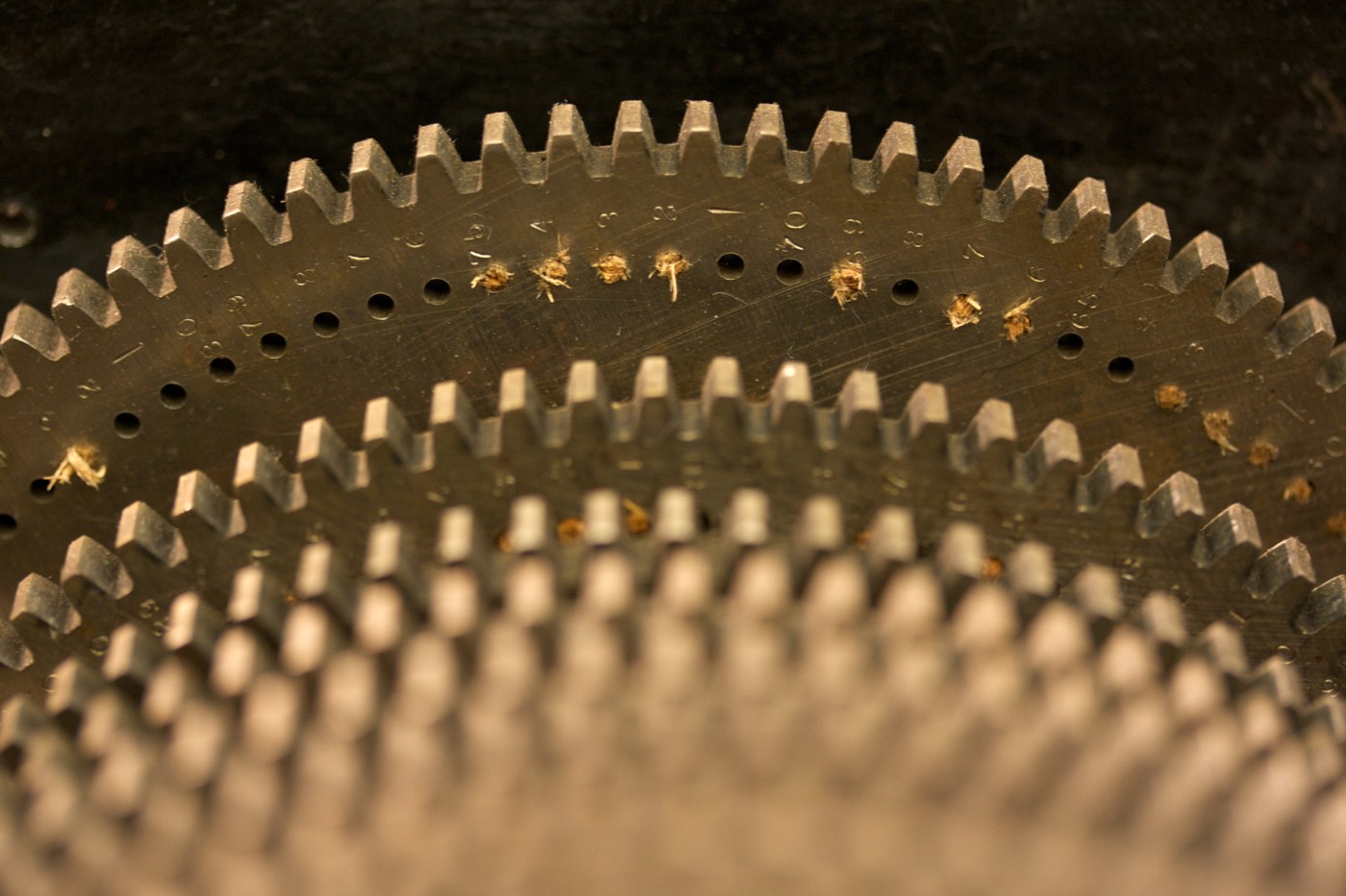
- “At the base of each tooth on each driven gear, holes are drilled at a constant distance from the periphery, this distance being the same for all gears. These holes are about 2 millimeters in diameter and correspond to the numbers 0, 1, 2, …, p − 1 modulo p.” Unwanted residues are “stopped up with wooden pins”.
- “The gears are mounted parallel to one another and have a common line of tangency so that if a beam of light from an incandescent lamp shines through a hole in any gear it is transmitted or blotted out by the next gear.”
- The flash “lasts only a ten thousandth of a second”. A six-stage amplifier multiplies the photocell’s output “by a factor of 700000000” to operate “a delicate thermionic relay, the first of a series of three relays which finally stops the machine.”
- To read a stop the operator “substitutes the human eye for the photo-electric cell, and by reversing the machine very slowly, brings it back to the exact position where the light shines through. He then reads the number of teeth by means of a revolution counter.”
- The machine examines “300000 numbers per minute” — five thousand a second.
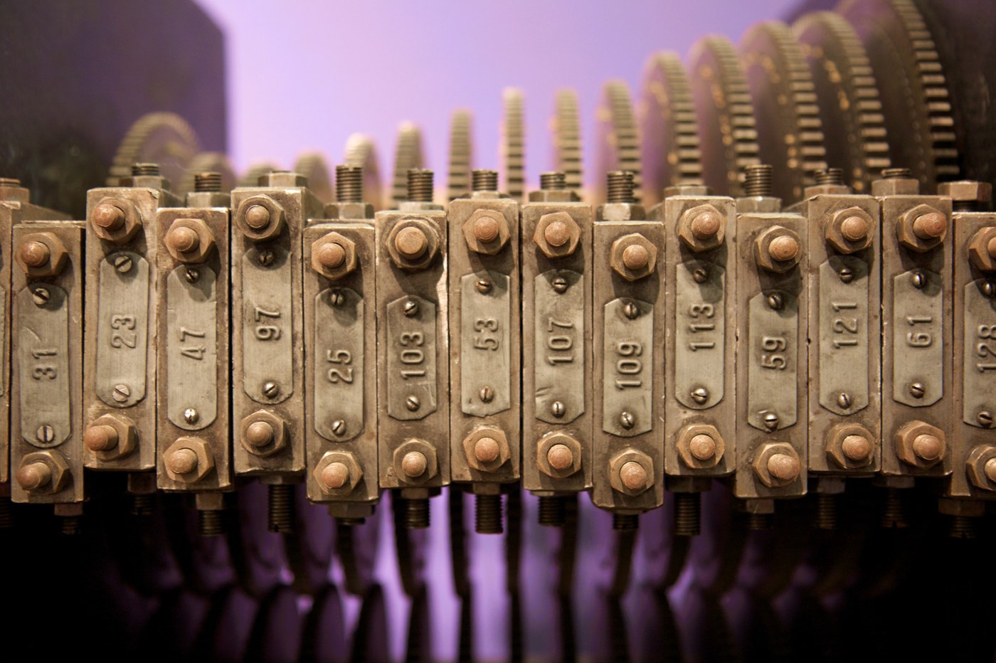
R. F. Lukes’s 1995 thesis adds the layout (A Very Fast Electronic Number Sieve, University of Manitoba, p. 15): fifteen driving gears of 100 teeth on one shaft, each meshing with two modulus gears; the thirty modulus gears on individual axles in two sets of fifteen on either side of the drivers; and “a pair of prisms used to redirect the light beams from the first set of 15 modular gears to the second.” Photographs of the surviving machine at the Computer History Museum (object X85.82, 275 lb, without its detector and amplifier) show exactly that: an upper row of labelled bearing blocks, a central row of drivers and a lower row.
D. N. Lehmer’s account of the first demonstration (“Hunting Big Game in the Theory of Numbers,” Scripta Mathematica 1, 1932; transcription) supplies the trouble: an amplifier so sensitive that “a slight jar, an infinitesimal variation in the electric current, the turning off of an electric appliance or even a hasty word from an attendant would send it off into a temperamental fit,” moved behind a brick wall into “a coffin of celotex”, and finally traced, with a loudspeaker, to a short-wave radio amateur nearby.
12.3 The Design Brief
The reproduction must:
- step thirty residues together, each gear advancing one tooth — one residue — per step;
- hold an acceptable-residue pattern per gear as open and plugged holes, changeable for each problem;
- pass light only when every gear presents an open hole on the beam;
- detect a flash that, at Lehmer’s speed, lasts well under a tenth of a millisecond;
- record the step count exactly at the flash, however far the machine coasts afterwards;
- reach Lehmer’s 5,000 steps a second eventually, but start somewhere that forgives a first build.
The two speed targets are:
Table 1 — The two speed targets are
| Target | Gears | Steps/s | Driver shaft (100-tooth drivers) | Tooth-line speed (module 1.5) | Light window per hole |
|---|---|---|---|---|---|
| Stage 1: first build | printed PETG | 500 | 5 rev/s, 300 rpm | 2.4 m/s | ≈ 640 µs |
| Stage 2: stretch | CNC-cut aluminium | 2,000 | 20 rev/s, 1,200 rpm | 9.4 m/s | ≈ 160 µs |
| Stage 2: Lehmer | CNC-cut aluminium, balanced | 5,000 | 50 rev/s, 3,000 rpm | 23.6 m/s | ≈ 64 µs |
At 500 steps a second the gears turn at a few revolutions a second, printed plastic is entirely adequate, alignment tolerances are generous, and Lehmer’s own problems take minutes rather than seconds (Volume 14). The plan is staged accordingly: Stage 1 is the whole machine with printed PETG gears, designed for 500 steps a second; Stage 2 replaces the gears with aluminium ones cut on the CNC router from the same drawings, for the higher speeds. Everything else — hanger plates, axles, bearings, optics, detector, controller — is built once, for Stage 2, from the start.
12.4 The Gear Set
12.4.1 Tooth counts
Lehmer says every gear has a multiple of its prime as its tooth count, with the counts between 67 and 128. The exact count for each gear is not in any source this series has read (the 1933 Monthly paper, “A photo-electric number sieve,” was not available; see Volume 7). The labels on the surviving machine’s bearing blocks include 128, 81, 25 and 121 where the smallest primes would be, and Lehmer’s worked example in the 1934 paper uses moduli 9, 25, 49 and 121 “instead of 3, 5, 7, and 11”. kbsriram, following Lukes, gives the moduli as 64, 27, 25, 49 and the primes 11 to 113.
The reproduction resolves this by making every gear’s tooth count a multiple of its modulus in Lehmer’s 67–128 range, and noting that a gear of N teeth serves any modulus that divides N: the 128-tooth gear serves 128 or 64, the 81-tooth gear 81 or 27, the 121-tooth gear 121 or 11, the 98-tooth gear 49 (or 7). One set of thirty gears therefore runs both the moduli on the surviving machine’s labels and the moduli kbsriram and Lukes report.
Table 2 — Tooth counts
| Gear for | Teeth | Also serves | Pitch Ø (mm) | Tip Ø (mm) | Hole radius (mm) |
|---|---|---|---|---|---|
| 2 | 128 | 64, 32 … | 192.0 | 195.0 | 92.1 |
| 3 | 81 | 27, 9 | 121.5 | 124.5 | 56.9 |
| 5 | 75 | 25 | 112.5 | 115.5 | 52.4 |
| 7 | 98 | 49 | 147.0 | 150.0 | 69.6 |
| 11 | 121 | 11 | 181.5 | 184.5 | 86.9 |
| 13 | 78 | 117.0 | 120.0 | 54.6 | |
| 17 | 68 | 102.0 | 105.0 | 47.1 | |
| 19 | 76 | 114.0 | 117.0 | 53.1 | |
| 23 | 69 | 103.5 | 106.5 | 47.9 | |
| 29 | 87 | 130.5 | 133.5 | 61.4 | |
| 31 | 93 | 139.5 | 142.5 | 65.9 | |
| 37 | 74 | 111.0 | 114.0 | 51.6 | |
| 41 | 82 | 123.0 | 126.0 | 57.6 | |
| 43 | 86 | 129.0 | 132.0 | 60.6 | |
| 47 | 94 | 141.0 | 144.0 | 66.6 | |
| 53 | 106 | 159.0 | 162.0 | 75.6 | |
| 59 | 118 | 177.0 | 180.0 | 84.6 | |
| 61 | 122 | 183.0 | 186.0 | 87.6 | |
| 67–113 (13 primes) | the prime itself | 100.5–169.5 | 103.5–172.5 | 46.4–80.9 | |
| Driver (×15) | 100 | 150.0 | 153.0 | — |
Dimensions are for module 1.5 mm, 20° pressure angle, full-depth teeth, with 2 mm holes; they are the output of the generator script described below. The smallest gear has 67 teeth and the largest 128, as Lehmer’s did.
12.4.2 Module
Lehmer’s numbers fix his tooth size. At 300,000 teeth a minute and 1,700 metres a minute, each tooth is 1,700 / 300,000 m = 5.67 mm of circular pitch, a module of about 1.8 mm; his 128-tooth gear would have been about 231 mm across and his 100-tooth drivers about 180 mm. The reproduction uses module 1.5, the nearest common standard size below that: a 4.71 mm circular pitch leaves room for a 2 mm hole under each tooth with a solid web around it, keeps the largest gear (195 mm over the tips) inside a 220 mm printer bed and a small laser bed, and makes the whole stack about 17 per cent smaller than the original. Module 1.25 would work with smaller holes; module 1 would need 1.5 mm holes and is not recommended.
12.4.3 Material: printed PETG first, then aluminium
Table 3 — Material: printed PETG first, then aluminium
| Process | Material | Strengths | Problems |
|---|---|---|---|
| 3D printing (FDM) | PETG or PLA, 5 mm thick | cheap, fast, gears and holes in one part; ideal for 500 steps/s | tooth accuracy ±0.1–0.2 mm and some cumulative pitch error; creep under axle load; holes print undersize and must be reamed |
| Laser cutting | acrylic, 5–6 mm | accurate profile, fast, flat | acrylic transmits light — including “black” acrylic in the near-infrared; brittle around small holes; kerf taper |
| CNC router | aluminium 5052/6061, 4–5 mm | stiff, durable, closest to Lehmer’s steel; the only choice for 5,000 steps/s | slow to cut with a small end mill; burrs; the router must hold ±0.05 mm |
The transparency of acrylic deserves emphasis. A plugged hole must block the beam, and so must the gear body around it. Clear acrylic obviously fails; tinted and black cast acrylic often pass a large fraction of near-infrared light, so an IR source sees through them. Since this build’s source is a 940 nm IR LED (below), acrylic gears would be usable only if a sample of the actual sheet passed the opacity test described below, or after painting both faces matt black.
The plan is staged:
- Stage 1 — printed PETG. All thirty modulus gears and the fifteen drivers printed in an IR-opaque PETG (see the opacity check below), printed flat at 100 per cent infill, holes printed 0.2 mm undersize and reamed to 2.0 mm. Run at 500 steps a second. This stage proves the geometry, the alignment procedure, the optics and the controller cheaply, and a misprinted gear costs an hour and a few cents.
- Stage 2 — CNC-cut aluminium. Once the printed machine runs Lehmer’s problems correctly, cut the gears in 5052 or 6061 aluminium on the CNC router from the same DXF files, holes drilled in the indexing jig described below, and raise the speed towards 2,000 and then 5,000 steps a second. The drivers can be replaced first, since they carry every mesh; then the modulus gears, all thirty or the most-used ones first. Aluminium is opaque, so the IR check does not arise again.
Laser-cut acrylic is not part of the plan, for the reason above.
At 5,000 steps a second the tips of a 128-tooth gear move at about 24 m/s and the gear turns at nearly 2,400 rpm. Printed gears at that speed are not safe; aluminium gears must be balanced and the whole stack guarded.
12.4.4 IR opacity: test the filament before printing the set
The beam is 940 nm infrared (below), and colour is no guide to what a plastic does at 940 nm. Some black plastics pass near-infrared freely — IR-transmitting black acrylic is made for exactly that, as the window over a remote-control receiver — because a black dye can absorb visible light and pass the near-infrared, where a carbon-black pigment absorbs both. Filament makers do not generally publish transmission at 940 nm, and this series found no published measurement for black PETG. So the filament is chosen by test, not by colour or by datasheet:
- Print a test coupon of the candidate filament at gear thickness (5 mm), with the same nozzle, layer height and 100 per cent infill as the gears, flat on the bed as the gears will be. Drill and ream one 2.0 mm hole in it, and fit a plug of the kind that will be used (toothpick, dowel or printed plug) in a second reamed hole.
- Measure it with the actual optics: the TSAL6200 at its working current behind its pinhole and lens, and the BPW34 and transimpedance amplifier described below, at the gain chosen for the machine. Record the amplifier output (a) with the path open, (b) with the LED off, (c) through the solid coupon, (d) through the plugged hole.
- Accept the filament only if (c) and (d) are indistinguishable from (b) — in practice, less than about 1 per cent of (a). A plugged gear that leaks 1 per cent against a comparator threshold of 30–50 per cent of the full signal leaves a margin of thirty times or more.
Prefer a filament that is opaque by construction: carbon-black-pigmented black, or carbon-fibre-filled PETG, is the likely candidate, but the test decides. Run the same test on the plugs; wood and printed plugs are only as good as the measurement says. If no filament passes, paint both faces of each printed gear matt black or print it with an opaque core, and test again.
12.4.5 The holes
Every gear has one 2 mm hole under every tooth, on a circle a fixed depth h below the pitch circle — Lehmer’s “constant distance from the periphery”. The generator uses h = 1.25 m + d/2 + 1 mm = 3.875 mm for module 1.5 and a 2 mm hole, which puts the edge of each hole 1 mm inside the root circle. Hole i sits under tooth i and stands for residue i mod m, so a gear of k·m teeth carries each residue k times, and all k copies must be plugged or open together.
The holes must be placed relative to the teeth, not to the gear’s centre: a hole that is correct in radius but a few tenths of a millimetre out in angle relative to its tooth will be out of line on the beam whenever that tooth is in mesh. On a printed gear the slicer places them together. On a machined gear, drill or ream the holes in a simple indexing jig that locates each hole from the gear’s own teeth: a fixed pawl engages a tooth space, a drill bush sits at the hole position above it, and the gear is turned one tooth at a time. Any cumulative pitch error in the teeth then appears identically in the holes, and cancels on the beam.
Engrave or print the residue number beside each hole, as Lehmer did — the numbers are visible on the original gears — so that plugging a problem is a matter of reading, not counting.
12.4.6 Plugs
Lehmer stopped the holes with wooden pins; visitors to the surviving machine see the broken ends of toothpicks still in some holes. Round wooden toothpicks are close to 2 mm at their widest and wedge themselves into a 2 mm hole; trimmed flush on both faces they are light, cheap and quick. For a reusable alternative, cut 2 mm beech dowel into 6 mm lengths, or print tapered plugs in the same IR-opaque PETG as the gears. Whatever the plug, it must pass the IR-opacity test above. At 500 steps a second a friction-fit plug is secure; at 5,000 the centrifugal load on a plug near the rim of the largest gear is a few hundred times its weight, and plugs should be tapered and pushed in from the side that the gear’s own motion would press them into.
12.5 The Arrangement: Why One Beam Passes Every Gear
The most interesting design question in the machine is geometric. Thirty gears of thirty different sizes must turn at thirty different angular speeds — one tooth per step each — and yet present their holes on a single straight beam. Two arrangements suggest themselves and both fail:
- All gears on one shaft. Then they turn at the same angular speed, and a 67-tooth gear would advance one tooth per step while a 128-tooth gear advanced 1.9 teeth. That is not a sieve.
- Each gear on its own axle, centres in a line. Then the hole circles have different radii about different centres, and a straight line parallel to the axles meets each circle at a different place.
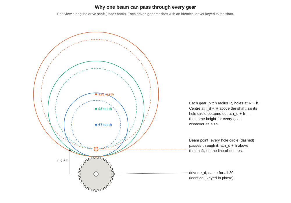
Lehmer’s solution, in his phrase, is that the gears “have a common line of tangency”. Every modulus gear meshes with an identical driver keyed to one shaft, so every gear’s pitch circle touches the same cylinder — the drivers’ pitch cylinder — along a line on the side facing the gears. Every gear’s centre lies on the far side of that line at a distance equal to its own pitch radius R. Now drill each gear’s holes at the same depth h below its pitch circle, on radius R − h. The point of each hole circle nearest the drive shaft is at
(rd + R) − (R − h) = rd + h
from the shaft axis, where rd is the driver’s pitch radius. The gear’s own size cancels. Every hole circle, of every size, passes through the same point in the plane — and, gear after gear along the shaft, through the same straight line parallel to it. The beam runs along that line, just outside the drivers’ tips. And because every driver is identical and keyed to the same shaft, every gear advances exactly one tooth per tooth of the drivers: one step, one residue, for all thirty.
This is why the holes are “at the base of each tooth” and “at a constant distance from the periphery, this distance being the same for all gears.” The sentence is the whole design.
12.5.1 Two banks and a pair of prisms
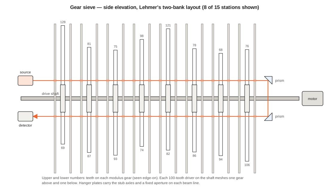
With one driver per gear, thirty gears in a row need thirty drivers on a long shaft. Lehmer halved it: each 100-tooth driver meshes with one gear above it and one below, so fifteen drivers carry thirty gears. The upper gears’ holes meet one beam line above the shaft, the lower gears’ holes another below it, mirror images about the shaft. A pair of prisms at the far end turns the beam through 180° from the upper line to the lower, so source and detector sit together at the near end (Lukes 1995, p. 15). The reproduction copies this layout exactly. Two right-angle prisms or two 45° front-surface mirrors on adjustable mounts serve; mirrors are cheaper and easier to adjust.
The fold doubles the beam’s length to about a metre and puts all thirty gears in series in one optical path, which is what the sieve requires.
12.5.2 Supporting thirty axles
Each modulus gear needs its own axle, and the axles cannot run through their neighbours: a large gear’s disc covers the place where a smaller neighbour’s axle would have to be. Lehmer used a separate bearing block for every gear. The reproduction uses hanger plates: one plate between each pair of stations, cut from 6 mm aluminium (CNC) or 6 mm plywood (laser), standing across the shaft. Each plate:
- is bored for the drive shaft, which passes through every plate and is supported by a bearing in every third plate;
- carries two stub axles (8 mm ground steel, cantilevered about 12 mm) for the upper and lower gears of the station beside it, in slots that let each axle move along the line of centres to set the mesh;
- has a 2.5 mm aperture on each beam line — a baffle that blocks stray light between gears and gives a fixed reference for alignment.
Each gear runs on a flanged 688 ball bearing (8 × 16 × 5 mm) pressed into a 16 mm bore. Set each mesh with a strip of 0.1 mm shim or paper between the teeth, then tighten the axle. The 100-tooth drivers are keyed or pinned to a 10 mm or ⅜ in shaft in identical angular phase — all fifteen with a tooth on the same line — which is what makes all thirty gears cross the beam in step.
Backlash needs one more part. A gear that is free to rock through its backlash can drift a few tenths of a millimetre either way along the beam. At speed, bearing drag keeps every gear lagging its driver against the same tooth face; at rest, and especially when the machine is reversed to find a stop, it does not. A light drag on each gear — a felt pad or a small O-ring bearing on the gear face from the hanger plate — keeps every gear loaded against its driver in both directions and costs almost nothing in power.
12.6 Optics
12.6.1 Source
Lehmer used an incandescent lamp, “originally supplied by an automobile headlight lamp” according to the caption of a Computer Museum photograph (The Computer Museum Report, Spring 1983, p. 2). The reproduction uses an infrared LED: the Vishay TSAL6200, a 940 nm emitter in a 5 mm package (datasheet), driven at constant current behind a 1 mm pinhole and a short-focus lens. It is matched to the BPW34 photodiode below, whose sensitivity peaks near 900 nm; it is insensitive to room light once the detector has an IR-pass filter or is simply enclosed; and it is safe to look along the path. An LED is not a point source, so the beam through the pinhole and lens is a millimetre or so across rather than the half-millimetre a laser would give; the coincidence window below is computed for 0.5 mm and is about two-thirds of that with a 1 mm beam, still ample at 500 steps a second. The cost of IR is that the beam is invisible, which is why the gears must be tested for IR opacity (above) and why alignment is done mechanically first (below).
Two alternatives are worth a line each. A red laser diode module of Class 2 (under 1 mW) gives a visible, narrow beam and is useful as a temporary alignment aid in the source’s mount; avoid the common 5 mW Class 3R modules. An incandescent lamp with a condenser lens is the faithful choice, but gives a weak, warm, slowly varying signal that the threshold would have to track.
12.6.2 Apertures and the coincidence window
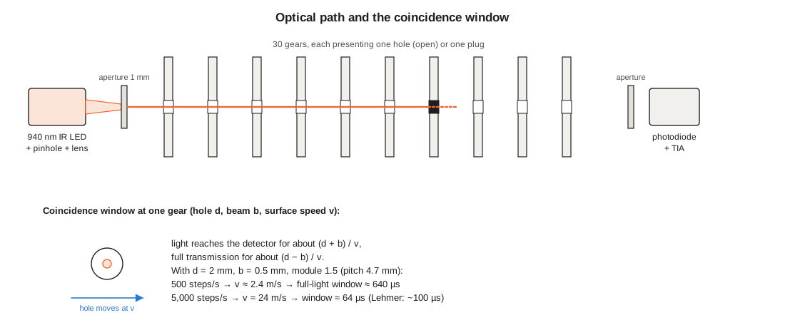
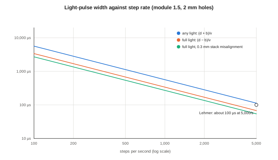
Light reaches the detector only while every gear’s hole overlaps the beam. For one gear with a hole of diameter d, a beam of diameter b and a hole speed v, some light passes for about (d + b)/v and the full beam for about (d − b)/v. With 2 mm holes, a 0.5 mm beam and module 1.5:
- at 500 steps a second (v ≈ 2.4 m/s), full transmission lasts about 640 µs;
- at 5,000 steps a second (v ≈ 24 m/s), about 64 µs — the same order as Lehmer’s “ten thousandth of a second”.
Across thirty gears the common window is the overlap of thirty individual windows, each displaced by that gear’s alignment error. If the holes are all within ±0.3 mm of the beam, the common full-light window shrinks by 0.6 mm of travel — to about 80 per cent of the single-gear value. If they are within ±0.75 mm, it shrinks to nothing, and only partial light ever reaches the detector. This is the alignment budget: every hole within ±0.3 mm of the beam line, and a detector threshold set low enough (30–50 per cent of the all-open signal) to accept partial coincidence.
Narrowing the beam widens the window but costs light. With the IR LED, a 1 mm source pinhole and a small aperture in front of the photodiode set the effective beam at roughly 0.5–1 mm. The hanger-plate apertures (2.5 mm) are deliberately larger than the holes so that they never limit the window.
12.6.3 Why alignment across thirty discs is hard
Every one of these errors moves a hole off the beam, and they add:
- Hole position on the gear — drilling or printing error relative to the tooth (±0.05 mm machined, ±0.1–0.15 mm printed).
- Gear runout — the bore not concentric with the pitch circle (±0.05–0.1 mm).
- Axle position — each slotted axle set by hand to mesh (±0.1 mm along the line of centres moves the hole by the same amount).
- Backlash — up to ±0.1 mm unless each gear is dragged (above).
- Driver phase — fifteen drivers keyed to one shaft; an error of 0.5° in one driver moves its two gears’ holes by about 0.65 mm. Pin the drivers, do not rely on set screws.
- Beam straightness and fold — the prisms must return the beam exactly along the lower line.
- Thermal and creep — printed gears grow and creep; a machine aligned cold may drift warm.
The sum of reasonable printed-gear errors is about ±0.3 mm — exactly the budget. That is the honest reason to run printed gears at 500 steps a second, with a generous threshold, and to cut the gears in aluminium before chasing Lehmer’s speed. It is also why Lehmer’s account dwells on “every detail of the construction had to be very delicately adjusted.”
12.7 Detection Electronics
12.7.1 Photodiode and transimpedance amplifier
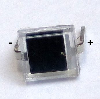
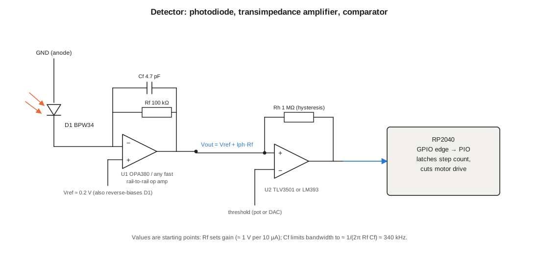
The detector is a silicon PIN photodiode, the Vishay BPW34 (datasheet): a 7.5 mm² active area, peak sensitivity at 900 nm with useful response from 430 to 1,100 nm (well matched to the 940 nm LED, and usable with a red alignment laser), and a 100 ns rise time. Its photocurrent is converted to a voltage by a transimpedance amplifier: an op-amp with a feedback resistor Rf, whose output is Vref + Iph·Rf. The TI OPA380 is designed for exactly this (datasheet: 90 MHz gain-bandwidth, transimpedance bandwidth above 1 MHz, single 2.7–5.5 V supply); any fast rail-to-rail op-amp will do at 500 steps a second.
Choose Rf for the source. The IR LED through a pinhole delivers tens of microamps of photocurrent or less, so Rf = 100 kΩ–1 MΩ; set it so the all-open signal is a volt or two. (A red alignment laser of about 1 mW gives hundreds of microamps and would need 1–10 kΩ; drop the gain while it is in use.)
A small capacitor across Rf (a few picofarads) keeps the amplifier stable and sets its bandwidth; with 100 kΩ and 4.7 pF the bandwidth is about 340 kHz, ample for a 64 µs pulse. Lehmer needed six valve stages and a gain of 700,000,000 because his photocell was “very inefficient” and his lamp was an incandescent bulb; a PIN diode and an IR LED matched to it need one op-amp. That difference — not cleverness — is why the reproduction’s electronics fit on a square inch.
12.7.2 Comparator and controller
The amplified signal goes to a comparator with a little hysteresis: the TI TLV3501 (4.5 ns, push-pull output, 2.7–5.5 V; datasheet) is fast enough for anything, and the ubiquitous LM393 (datasheet) is adequate at these speeds if its open-collector output is given a pull-up. The threshold is a trimmer or a filtered PWM output from the controller, set to 30–50 per cent of the signal with every hole open.
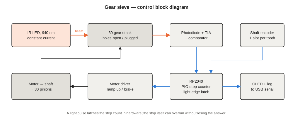
The comparator output drives a GPIO on a Raspberry Pi Pico. As in the chain sieve, one PIO state machine counts encoder pulses — one per driver tooth — and latches the count on the comparator’s rising edge; the main program tests the candidate, logs false stops, and on a true answer stops the motor and reports. The latch is gated by the encoder: a light edge is accepted only in a window centred on the moment the teeth are in line. Lehmer’s radio amateur could stop his machine at any time; a gated detector ignores a burst of interference that does not coincide with a step.
Keep the photodiode, amplifier and comparator together in a small shielded box at the detector end, with the photodiode’s leads a few millimetres long, and run only the comparator’s logic output to the Pico. The 1932 amplifier needed a brick wall; this one needs a tin box and short leads.
12.7.3 Counter and encoder
The step count comes from the drive shaft: a disc with one slot per driver tooth — one hundred slots — read by an Omron EE-SX1041 slot sensor (datasheet), plus an index slot once per revolution. Cut the disc on the CNC from 1.5 mm aluminium (100 slots of 1.5 mm on a 60 mm radius) and lock it in phase with the drivers so that the middle of each slot coincides with the teeth being in line. At 5,000 steps a second the sensor sees 5 kHz, well inside its response; the PIO counts it without effort.
A mechanical revolution counter on the shaft, as Lehmer had, reads hundreds of steps per revolution and is a useful independent check.
12.7.4 Motor and stopping
At 500 steps a second (Stage 1) the drive shaft turns at 300 rpm; at 5,000 (Stage 2, aluminium gears), at 3,000 rpm. A brushed DC motor of 50–100 W with a belt drive covers the first; a small brushless motor with its own controller, or a DC motor at higher speed, the second. The motor driver needs a brake (short-braking H-bridge) and the controller ramps the speed up and down.
Overrun is handled as in the chain sieve: the count is latched at the flash, so the stop position does not matter, and the controller can then walk the shaft back slowly to the latched step — Lehmer’s “reversing the machine very slowly” — so that the open holes are all on the beam and the light shines through for the operator to see. At Lehmer’s speed his machine coasted a long way after the relays opened; the latch makes that irrelevant.
12.8 Generating the Gears
12.8.1 The script: gear_sieve_gears.py
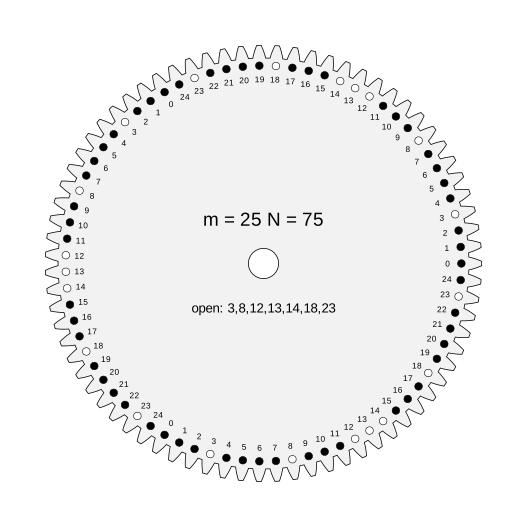
Every gear in the set, and the driver, is drawn by 03-outputs/cad/gear_sieve_gears.py (Python 3, standard library only). For a modulus and tooth count it computes an involute spur-gear outline (module and pressure angle as options), places one hole under every tooth at the fixed depth, labels each hole with its residue, and writes three files:
- SVG in millimetres — for the laser, for inspection, and for printing a 1:1 template;
- DXF (AutoCAD R12, with layers CUT, HOLES and ENGRAVE) — for CNC and laser CAM;
- OpenSCAD source — a
linear_extrudeof the outline minus the bore and holes, to render and export as STL for printing.
Given a problem’s acceptable residues it also writes a setup sheet: the gear drawn with open holes white and plugged holes black, to lay beside the gear while plugging it.
python3 gear_sieve_gears.py --all --pinion 100 --out gears
python3 gear_sieve_gears.py --modulus 25 --teeth 75 --open 3,8,12,13,14,18,23 --tag M79
The first command writes the thirty modulus gears and the 100-tooth driver; the second writes the plug map for the 25 gear on Lehmer’s 2⁷⁹ − 1 problem (the residues come from lehmer_runs.py; Volume 14). Both ran when this volume was written; the table of tooth counts and diameters above is the first command’s output. The SVG and DXF outputs were rendered and inspected. OpenSCAD is not installed on the machine where the script was written, so the .scad files have not been rendered there; they are plain polygon() and cylinder() source and should render in any recent OpenSCAD. Options set the hole diameter (--hole), the web between hole and root (--web), the bore (--bore; use 16 for a 688 bearing) and the thickness (--thickness).
12.9 Bill of Materials
Prices are estimates in US dollars, October 2026, for orientation only. The main total is Stage 1 (printed PETG gears); Stage 2 adds the aluminium.
Table 4 — Bill of Materials
| Item | Specification | Qty | Est. unit | Est. total |
|---|---|---|---|---|
| Modulus gears (Stage 1) | printed IR-opaque PETG, module 1.5, 5 mm, 67–128 teeth | 30 | $2 (filament) | $60 |
| Driver gears (Stage 1) | printed IR-opaque PETG, 100 teeth | 15 | $3 | $45 |
| IR-opacity test coupons | candidate PETG filaments, 5 mm coupons | 2–3 | $2 | $6 |
| Aluminium plate (Stage 2 gears) | 5052/6061, 5 mm, 600 × 600 mm (30 gears + 15 drivers) | 3 | $90 | $270 (Stage 2) |
| Bearings for gears | 688 flanged, 8 × 16 × 5 mm | 30 | $1 | $30 |
| Stub axles | 8 mm ground rod, cut to 25 mm | 30 | — | $25 |
| Drive shaft | 10 mm ground steel, 600 mm | 1 | $20 | $20 |
| Shaft bearings | 10 mm flanged or pillow block | 4 | $6 | $24 |
| Hanger plates | 6 mm aluminium or plywood, CNC/laser | 16 | — | $60 |
| Base and frame | T-slot extrusion and plate | 1 lot | — | $100 |
| Plugs | round wooden toothpicks or 2 mm beech dowel | 1 box | $5 | $5 |
| Light source | Vishay TSAL6200 940 nm IR LED + 6 mm lens + pinhole | 2 | $3 | $6 |
| Alignment aid (optional) | red laser diode module, Class 2 (≤1 mW) | 1 | $10 | $10 |
| Prisms or mirrors | right-angle prisms or 45° front-surface mirrors, adjustable mounts | 2 | $15 | $30 |
| Photodiode | Vishay BPW34 | 2 | $1.50 | $3 |
| TIA op-amp | TI OPA380 (or any fast RRIO op-amp) | 2 | $5 | $10 |
| Comparator | TI TLV3501 (or LM393) | 2 | $3 | $6 |
| Detector enclosure | small die-cast box, shielded cable | 1 | $15 | $15 |
| Controller | Raspberry Pi Pico | 1 | $5 | $5 |
| Encoder | Omron EE-SX1041 + CNC-cut 100-slot disc | 2 sensors | $5 | $10 |
| Display | 0.96 in SSD1306 OLED | 1 | $8 | $8 |
| Motor | brushed DC, 24 V, 50–100 W, with belt drive | 1 | $70 | $70 |
| Motor driver | brushed-DC H-bridge, ≥10 A | 1 | $20 | $20 |
| Power supply | 24 V 5 A plus 5 V for logic | 1 | $35 | $35 |
| Guard | 3 mm polycarbonate enclosure, interlock switch, e-stop | 1 lot | — | $90 |
| Sundries | felt pads, O-rings, fasteners, wiring | 1 lot | — | $50 |
| Total, Stage 1 (printed PETG gears) | ≈ $750 | |||
| Total, after Stage 2 (aluminium gears) | ≈ $1,050 |
12.10 Assembly
- Pass the IR-opacity test with the chosen filament and plugs, then print the gears and drivers (Stage 1). Ream every hole to 2.0 mm with a hand reamer; press in the 688 bearings. Check each gear’s tooth count against its label.
- Cut the hanger plates with the shaft bore, the two axle slots and the two beam apertures, all from one CAD drawing so the apertures are in the same place on every plate. Number them.
- Build the frame: base, end plates, and the drive-shaft bearings. Thread the shaft through all sixteen hanger plates, sliding the fifteen drivers on between them in order, and pin each driver to the shaft with every driver’s tooth 0 on the same line (a straightedge across the teeth of all fifteen).
- Fit the upper gears, one station at a time: axle in its slot, gear on the axle, mesh set with a 0.1 mm shim, axle tightened. Then the lower gears.
- Fit the drag pads so each gear is lightly loaded against its driver.
- Fit the encoder disc and sensor at the drive end, and the motor and belt.
- Mount the source, prisms (or mirrors) and detector on adjustable mounts at the ends.
- Wire the detector box, the Pico, the motor driver and the interlocks. Close the guard.
12.11 Alignment and Calibration
12.11.1 Mechanical alignment with a rod
Before any light is involved, align the holes mechanically. With every hole open (no plugs), turn each upper gear on its axle (lifting it out of mesh by slackening its axle) until its residue-0 hole sits on the upper beam line, and re-mesh. A 2 mm ground alignment rod about 400 mm long, pushed through the first hanger plate’s aperture, will then slide through every upper gear’s 0 hole and every plate’s aperture, as a bore-sighting rod slides down a barrel. Any gear it will not pass is out — in axle position, in phase, or in hole position — and is corrected before going on. Repeat for the lower bank.
This also sets every gear’s zero: with the rod through the 0 holes, set the encoder count to zero and mark each gear’s 0 hole against a pointer on its hanger plate. Lehmer’s operator set his gears to zero for every problem in the same way, by number.
12.11.2 Optical alignment
Remove the rod and switch on the IR LED. Its beam is invisible, so align it by the detector: with every hole open and the shaft at zero, adjust the source, then the first prism or mirror (turning the beam down to the lower line), then the second (sending it back along the lower apertures), each for maximum amplifier output on a meter or oscilloscope. A phone camera often shows a 940 nm spot on a white card, and a Class 2 red laser in the source’s mount makes the first rough pass visible — but the final adjustment is always for peak signal from the IR LED itself. With every hole open and the shaft at zero, the detector should then see the full signal.
With no plugs fitted, every gear presents an open hole on every step, so every step is a coincidence and the signal should pulse once per step as the shaft is turned by hand. Between steps — with the teeth half a pitch out of line — it should fall almost to zero. A pulse that is weak on particular steps points to one gear whose hole is off the line at that tooth: plug every hole of a suspect gear except one and watch whether that one step’s pulse recovers.
12.11.3 Electronic calibration
- With all holes open and the motor running at 50 steps a second, the comparator must fire on every step, and the Pico must log one latched count per encoder pulse. Adjust the encoder disc’s phase until the light pulse sits in the middle of the encoder window.
- Record the amplifier’s peak output with all holes open; set the comparator threshold to 40 per cent of it.
- Plug all holes on one gear, and run: the comparator must never fire. Repeat for every gear in turn (or at least for the gears at both ends of each bank and at the prism). This is the gear sieve’s equivalent of the chain sieve’s bus test, and it confirms on the assembled machine what the coupon test showed: every plug blocks and every gear body is opaque at 940 nm.
- Raise the speed in steps — 50, 100, 200, 500 steps a second — checking at each that every all-open step still fires (no missed coincidences) and that no blocked step fires (no false ones).
12.12 First Test Problems
12.12.1 The 7663 example again
The chain sieve’s test problem works unchanged: plug the 75-tooth gear (modulus 25) for b² + 7663 a square mod 25 and the 98-tooth gear (modulus 49) for the same mod 49, leave every other gear fully open, and run from zero. Use chain_tabs.py (Volume 11) to list the residues. The machine must stop first at a false stop and then at b = 9, where 9² + 7663 = 88². The arithmetic is trivial; the point is to see the beam pass two plugged gears and twenty-eight open ones on exactly the predicted steps.
12.12.2 Lehmer’s own first problem: 2⁹³ + 1
The first real problem should be the one the machine solved on 9 October 1932, a few days after the radio amateur was found: the cofactor N = 1,537,228,672,093,301,419 of 2⁹³ + 1. “The work of a quarter of a century had been done in less than a quarter of a minute,” D. N. Lehmer wrote of it. Lehmer’s 1934 paper sets it up in full: factors of N have the forms 93n + 1 and 8n + 1, so a = 69,192x + 1,239,854,518 with 0 ≤ x ≤ 37,010,176, and the machine seeks x for which
f(x) = 4,787,532,864 x² + 171,576,027,618,912 x + 10,553,711,710,905
is a square. Lehmer’s machine “stopped in about 3 seconds at x = 6886”, where f(6886) = 1,186,799,691², giving N = 529,510,939 × 2,903,110,321.
At 500 steps a second the reproduction should stop at x = 6,886 after 13.8 seconds, with no false stop before it on the full thirty-gear set (Volume 14 computes the stops for every configuration). The plug patterns for all thirty gears come from lehmer_runs.py, which builds them exactly as kbsriram’s problem driver does — including the reductions for the moduli that share factors with the step 69,192 = 2³ · 3² · 31² — and checks that x = 6,886 passes every gear.
Then, with the Stage 2 aluminium gears, try it at 5,000 steps a second. Lehmer’s machine took “about 3 seconds” and kbsriram’s ATtiny reproduction 1.41 seconds at that rate; 6,886 steps at 5,000 a second is 1.38 seconds.
12.13 What the Build Teaches
The gear sieve is the chain sieve with its two weaknesses removed: gears do not whip, and light does not bounce. What replaces them is a demand for precision. Thirty separate parts must agree to a few tenths of a millimetre, along a metre of beam, while turning at different speeds, and the agreement must last for hours. Building it shows why the geometry is the heart of the machine — one constant depth under the teeth makes thirty sizes of gear behave as one — and why Lehmer’s real difficulties were electrical: a 1932 photocell and valve amplifier needed a gain of seven hundred million and a brick wall. A modern photodiode needs neither. The next volume follows the idea one step further, to where the gears themselves become bit patterns in thirty small chips.
Next — Volume 13: Building the Tiny Sieve (ATtiny412 + RP2040). kbsriram’s electronic sieve: thirty modulus cards on a backplane, a shared clock and veto line, and an RP2040 that checks every survivor. It is ten thousand times faster than the gears and fits on a desk.
Comments (0)