Lorenz and Colossus · Volume 13
Lorenz and Colossus — Volume 13 — Building a Lorenz — Construction and a Message Sent
Wiring the twelve wheel modules, an isolated current loop for a real teleprinter, bring-up one wheel at a time, a verification procedure built on Tiltman's 1961 example and three real SZ42 messages from 2007, and a test message enciphered on the Bream wheels of April 1944, sent and read back
13.1 About This Volume
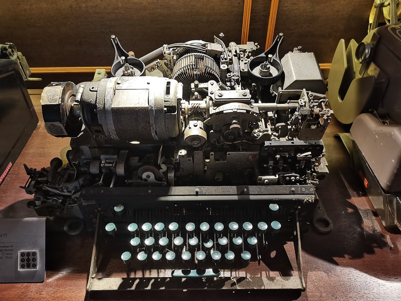
Volume 12 designed an electronic replica of the Lorenz SZ42: twelve wheel modules, each a knob and a small screen, a Raspberry Pi Pico 2 holding the 501 cams and stepping them by the SZ40, SZ42A and SZ42B rules, a control panel modelled on the original, and characters in and out over USB or a teleprinter loop. This volume builds it.
It runs in the order the bench needs: the wiring plan, bring-up one subsystem at a time, the isolated loop interface for a real teleprinter, the verification procedure, and finally a message — a teleprinter test line enciphered on the replica with the real wheel patterns of the Berlin–Rome link for 14 April 1944, sent, and read back by a second machine.
As in Volume 12, nothing here has been built yet. It is a construction plan and a test procedure. Every expected result quoted below — every cipher letter and wheel position — comes from the simulator, 03-outputs/tools/lorenz_sim.py, so a builder can check the replica against it at every stage.
13.2 Wiring
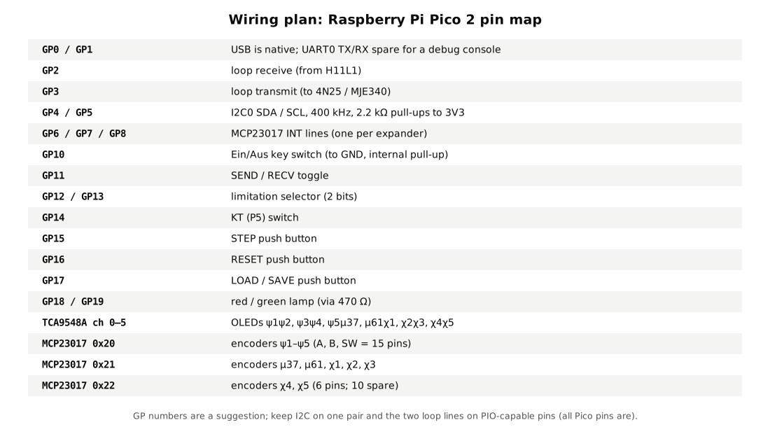
The replica has three kinds of wiring, and they are best kept physically apart.
The I2C bus. One pair of wires, SDA and SCL, from the Pico to the TCA9548A multiplexer and the three MCP23017 expanders, with 2.2 kΩ pull-up resistors to 3.3 V fitted once, near the Pico. From the multiplexer, six channels each run to two screens: ψ1 and ψ2 on channel 0, ψ3 and ψ4 on 1, ψ5 and μ37 on 2, μ61 and χ1 on 3, χ2 and χ3 on 4, χ4 and χ5 on 5. On each channel one screen keeps the default address 0x3C and the other is jumpered to 0x3D. Many SSD1306 modules carry their own pull-ups; with twelve of them in parallel through the multiplexer the effective pull-up can become too strong, so the module pull-ups on all but one screen per channel should be removed or left unsoldered. I2C is a short-distance bus. A row of modules a metre long is near its limit at 400 kHz, and if the screens misbehave the first remedy is to drop the clock to 100 kHz; the screens are the only thing that slows down.
The encoder lines. Each encoder’s A, B and push contacts run to an expander pin, with the common to ground; the expanders’ internal pull-ups are enabled in firmware. The first expander (0x20) takes ψ1–ψ5, the second (0x21) μ37, μ61, χ1, χ2 and χ3, and the third (0x22) χ4 and χ5. Each expander’s interrupt output runs to its own Pico pin.
The panel switches go directly to Pico GPIO pins, switched to ground, with internal pull-ups. The lamps are driven through 470 Ω resistors.
The fourth kind of wiring, the teleprinter loop, is not part of this harness at all: it lives on its own board behind its own isolation barrier, described below.
13.3 Bring-Up, One Wheel at a Time
Bring-up uses a small test firmware before the cipher firmware is loaded, so that each fault shows up alone.
- Bus scan. With nothing but the Pico, the multiplexer and the expanders connected, scan the bus. The scan must find exactly 0x20, 0x21, 0x22 and 0x70. A missing expander is almost always a wrong address jumper.
- Screens, a channel at a time. Connect one pair of screens, select its channel, and scan again: 0x3C and 0x3D must appear. Draw the wheel’s name on each. Repeat for all six channels. At the end every screen should show its own name —
ψ1 43throughχ5 23— in the machine’s order across the panel. - Encoders. For each knob in turn, turn it one detent clockwise and confirm that the count on its own screen rises by one, and that no other screen changes. A count that rises by two, or falls, means the A and B wires are swapped or the quadrature table is wrong. Push and confirm the press registers.
- Panel. Exercise each switch and confirm its state on a debug line over USB.
- Lamps. Red and green, each in turn.
Only when every wheel can be turned and every switch read does the cipher firmware go in.
13.4 The Teleprinter Loop
Over USB the replica needs nothing more. To work with a real teleprinter it needs an interface to a current loop.
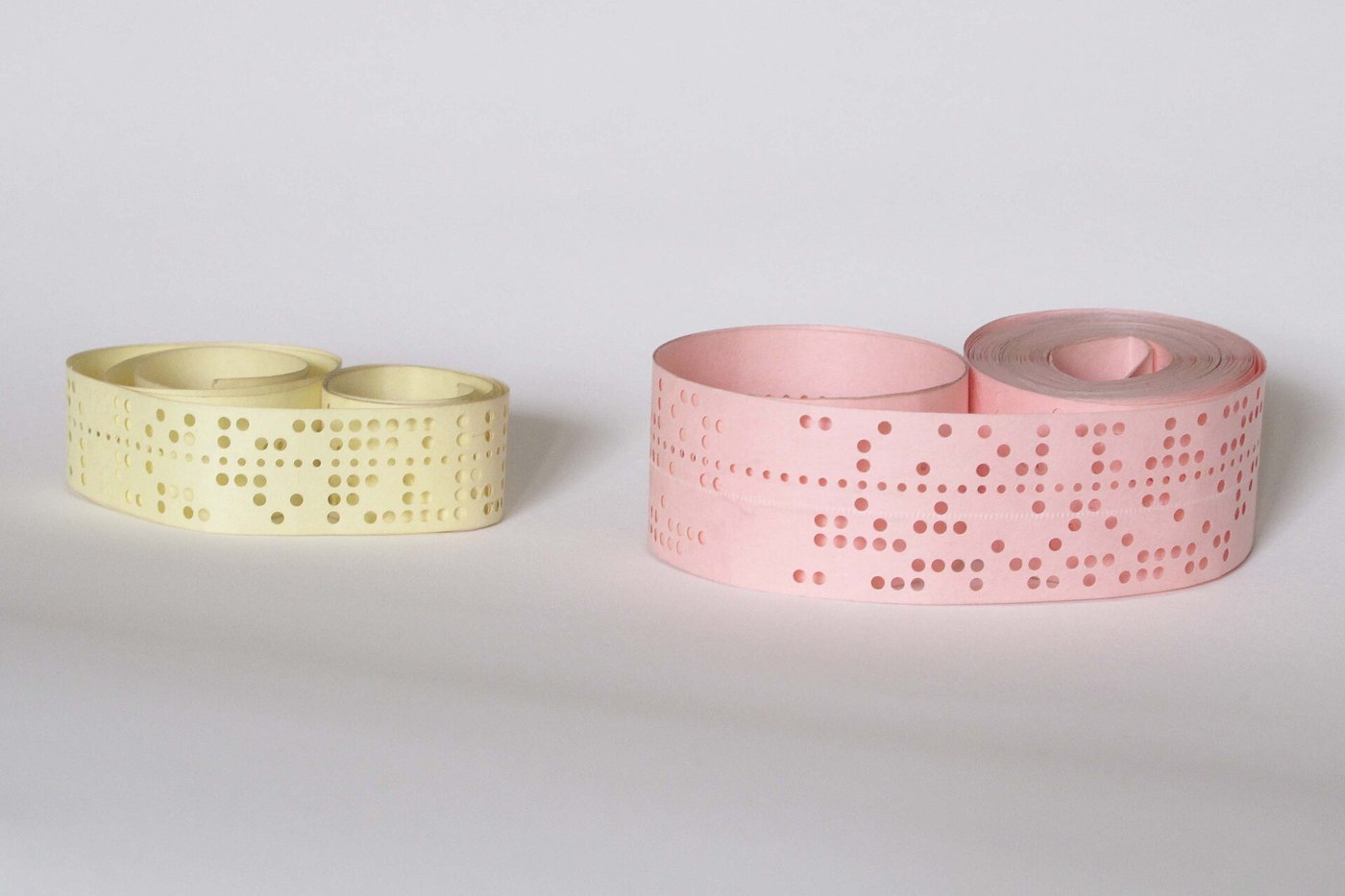
A start-stop teleprinter signals by switching a direct current on and off in a circuit that runs through its own keyboard contacts and its own printing magnet. Current flowing is mark — Bletchley’s cross; no current is space — a dot. With the line idle the loop carries current continuously. A character is a space of one unit (the start pulse), five units of mark or space for the five impulses, and a mark for one to one and a half units (the stop pulse). At 50 baud a unit is 20 ms. The German SZ42 manual gives “7.14 symbols per second”, a seven-unit character of 140 ms; many 50-baud machines use a one-and-a-half-unit stop pulse and 150 ms a character (Cipher Attachment 42, Provisional Descriptions, TICOM T663, CryptoCellar). The original SZ42 itself fed its local teleprinter from its own telegraph supply of about 100 V DC, at up to 125 mA (same source).
Loop currents and voltages vary by machine and by country. American Teletype machines commonly run a 60 mA loop (some 20 mA) at 45.45 baud; British and German machines of the period ran at 50 baud and often at 40 mA or with double-current (polar) signalling. The replica’s interface is built for the common single-current loop and is set to suit the machine on the bench. Restoring and powering a teleprinter, and building its loop supply, are covered in the Teletype, Tape and RTTY unit of the Dots & Dashes project (dots-and-dashes.fubsypoly.com); the interface here assumes a working machine and a working loop supply.
13.4.1 The design
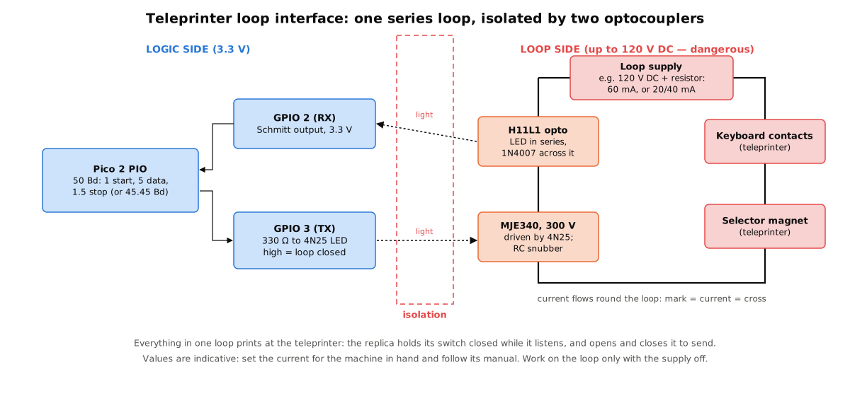
Everything sits in one series loop: the loop supply (typically a DC supply of around 100–120 V with a series resistor that sets the current), the teleprinter’s keyboard contacts, its selector magnet, and two elements of the replica.
- Receive. The LED of an H11L1 optocoupler sits in series with the loop, with a 1N4007 diode connected in reverse across it to protect it from reverse voltage and spikes. The H11L1 has a Schmitt-trigger output, so the Pico sees clean edges even when the loop current rises and falls slowly through the magnet’s inductance. Its output, on the 3.3 V side, goes to GPIO 2. When the teleprinter’s operator types, the keyboard contacts break the loop and the H11L1 reports each pulse.
- Transmit. An MJE340 transistor, rated at 300 V, sits in series with the loop as a switch. It is driven from the logic side through a 4N25 optocoupler, whose LED is lit from GPIO 3 through a 330 Ω resistor. With the LED lit the transistor conducts and the loop is closed (mark); with it dark the loop is open (space). An RC snubber across the transistor absorbs the spike from the magnet’s inductance each time the loop opens.
Because everything is in one loop, everything prints. When the replica transmits, the teleprinter’s magnet follows and the teleprinter prints what the replica sends; when the teleprinter’s keyboard sends, the replica must hold its own transistor on (loop closed) so that it does not interrupt the character it is trying to read. The firmware does this automatically: in RECV it holds GPIO 3 high; in SEND it ignores GPIO 2 except as a check that the loop is unbroken.
13.4.2 Safety
The loop side runs at a voltage that can kill. The interface board is laid out with the loop side and the logic side on opposite ends, joined only by the two optocouplers, with at least 6 mm of bare board between the two sides. The loop side is fused, enclosed, and connected with insulated, polarised plugs. The series resistor in a 120 V, 60 mA loop dissipates about 7 W and needs a power resistor rated well above that, mounted where it cannot be touched. Work on the loop only with the supply switched off and its capacitors discharged.
The values in the figure are indicative. The current must be set for the teleprinter actually connected, from its own manual.
13.4.3 The PIO programs
Two small PIO programs run the line. The transmitter takes a five-bit code from a FIFO and clocks out a start space, the five impulses (impulse 1 first) and a stop mark of 1 or 1.5 units. The receiver waits for a mark-to-space edge, waits half a unit, checks that the line is still at space (rejecting a glitch), then samples the line at the centre of each of the next five units and pushes the five bits into a FIFO. The unit time is set from the PIO clock divider: 20 ms for 50 baud, 22 ms for 45.45 baud.
13.5 Verification
The replica is checked against the simulator, and the simulator against published history. Each test below has an exact expected result; a test either passes or the replica is wrong. The expected results are from lorenz_sim.py and can be regenerated at any time.
13.5.1 Test 1 — Key files round trip
Load each of the three key files of the 2007 Cipher Event (03-outputs/tools/testdata/cipher_event_2007/*/key.txt) over USB, save it back, and compare. The files must be identical. This checks the 501 cams and twelve positions are stored and numbered correctly, from 1, as on the wheels.
13.5.2 Test 2 — Stepping
Load Tiltman’s Bream patterns of 14 April 1944 with his start positions — μ61 26, μ37 7; ψ1–ψ5 5, 31, 12, 50, 37; χ1–χ5 15, 2, 6, 18, 10 — and press STEP one hundred times. The twelve windows must then read, in the order χ1–χ5, μ61, μ37, ψ1–ψ5:
Table 1 — Load Tiltman's Bream patterns of 14 April 1944 with his start positions — μ61 26, μ37 7; ψ1–ψ5 5, 31, 12, 50, 37; χ1–χ5 15, 2, 6, 18, 10 — and press STEP one hundred times. The twelve windows must then read, in the order χ1–χ5, μ61, μ37, ψ1–ψ5
| Rule | χ1 | χ2 | χ3 | χ4 | χ5 | μ61 | μ37 | ψ1 | ψ2 | ψ3 | ψ4 | ψ5 |
|---|---|---|---|---|---|---|---|---|---|---|---|---|
| SZ40 (no limitation) | 33 | 9 | 19 | 14 | 18 | 4 | 5 | 23 | 45 | 22 | 5 | 39 |
| SZ42A (χ2 one back) | 33 | 9 | 19 | 14 | 18 | 4 | 5 | 43 | 18 | 42 | 25 | 59 |
The chi and motor wheels agree under both rules, as they must: the limitation touches only the psis. Under the SZ40 rule the psis moved 61 times in the 100 steps (ψ1 went once round its 43 cams and 18 places further, from 5 to 23); under the SZ42A rule they moved 81 times. A replica that passes the first row and fails the second has its limitation wrong; one that fails the chi columns has its stepping order wrong.
13.5.3 Test 3 — Tiltman’s twenty letters
With the same patterns and start, the limitation set to none, and the replica in letters mode, send 989UND989EINGESETZTE. The reply must be:
YXW9WIXNRPB+CVQN+O83
— the cipher text of J. H. Tiltman’s worked example (“The ‘Tunny’ Machine and Its Solution”, NSA, 1961, Fig. 5; CryptoCellar). This is a published wartime test vector: Tiltman worked it on the real Bream patterns, and the simulator reproduces every intermediate row of his figure (Volume 3). The power-up self-test already runs it, but running it through the panel and the USB path checks the input and output code as well.
Then RESET, set the limitation to χ2, and send the same text. The reply must be YXW9WIXNRPBCYFSEEHWT. The first ten letters agree with Tiltman’s; from letter 11 the SZ42A limitation releases the psis where the SZ40 held them (Volume 3).
13.5.4 Test 4 — Three real SZ42 messages
This is the strongest test available: real Lorenz traffic. In November 2007 The National Museum of Computing sent three messages enciphered on the Lorenz SZ42 by radio from the Heinz Nixdorf MuseumsForum in Paderborn, as a challenge to its rebuilt Colossus. Joachim Schüth received and broke them, and published his demodulated tapes, keys and decipherments (schlaupelz.de). Copies are in testdata/cipher_event_2007/.
- Load the 1600 UTC key (
1600UTC/key.txt: χ 36 27 2 1 23, μ 12 10, ψ 4 22 12 17 20, SZ42A). - Print the tape as Bletchley letters with
python3 lorenz_sim.py --cipher-event 1600UTCand send it to the replica in letters mode. - The reply, turned into text, must begin
GTU YLUCOMPUTER.MEDIZIN HIGHTECH FUR GESUNDHEIT UND LEBENSQUALITATand continue as German for 5,880 characters, identical to Schüth’s publishedplain.out. The odd letters at the start and here and there in the text are radio errors in the 2007 reception, not machine faults; the simulator and Schüth’s own program reproduce them identically.
Repeat with the 1200 UTC and 1700 UTC keys and tapes. With the limitation switched to none, none of the three should read: the first few characters may survive, but German text should not.
13.5.5 Test 5 — The unvalidated modes
For SZ42B and the P5 function no published message exists. The test is between the two implementations only: for twenty random keys and messages, the replica and the simulator must give the same cipher text in every mode. Passing this proves the replica matches the simulator; it does not prove either matches a wartime SZ42B. The test sheet should record that distinction.
13.5.6 Test 6 — The loop
With a teleprinter connected, put the replica in RECV with the limitation off and every cam set to a dot — a machine whose key is all / passes text straight through — and type RYRYRY. The same characters must come back and print. (R is •x•x• and Y is x•x•x, each the other with every impulse reversed, so RYRY changes every impulse at every character — the classic line test.) Then restore a real key.
13.6 A Message Sent
The demonstration is a full round trip, with a second “machine” at the far end. The receiving end can be a second replica, or the simulator running on a PC, which is how it is described here.
The key. Tiltman’s Bream patterns of 14 April 1944, his start positions, and the SZ42A limitation — real wartime wheel patterns, enciphering a message under the rule that Bletchley met from February 1943.
The message. A teleprinter test line rather than an invented military text:
RYRYRY THE QUICK BROWN FOX JUMPS OVER THE LAZY DOG 1234567890
In Bletchley’s letters, with spaces as 9, a shift to figures + before the digits (which on a teleprinter are the top-row letters QWERTYUIOP) and a shift back to letters 8 at the end, that is 63 characters:
RYRYRY9THE9QUICK9BROWN9FOX9JUMPS9OVER9THE9LAZY9DOG9+QWERTYUIOP8
Enciphering. With the replica at the start positions, in Ein and SEND, the message is typed or sent over USB. The replica sends:
+QXPYGXAGP+Y3RCKYMDDJT3YW+C+/SLGG98+VBVOCAIBIXE4SZYC+JCYWOTBESF
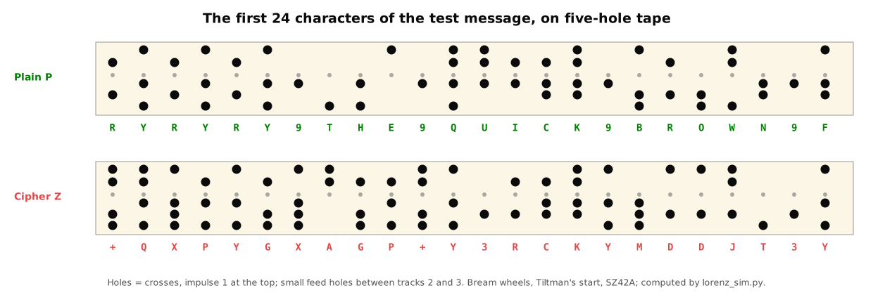
Three things can be seen in it. The six-letter RYRYRY, the most regular thing a teleprinter ever sends, has vanished into +QXPYG. The cipher is full of shift, space, carriage-return and line-feed characters (+, 8, 9, 3, 4), so a teleprinter printing it directly would jump between letters and figures and throw lines unpredictably; this is why the replica monitors cipher in letters mode, and why Tunny traffic was handled as tape. And at the end, the wheels stand at χ 37, 3, 11, 3, 4; μ 28, 14; ψ 17, 39, 16, 52, 33. The psis stood still after only 8 of the 63 characters.
Receiving. At the far end the receiving machine is set to the same patterns, the same start and the same limitation, and given the cipher. It returns:
RYRYRY THE QUICK BROWN FOX JUMPS OVER THE LAZY DOG 1234567890
and finishes at exactly the same twelve positions.
Getting it wrong. Two deliberate mistakes show what an operator’s error looked like at the receiving end.
- Wrong motor rule. Deciphering with the limitation switched off, the receiver produces
RYRYRY THEcorrectly — under both rules the psis happen to move identically for the first eleven characters — and then nonsense, with stray line feeds and figures. A receiver on the wrong rule loses everything after the first point where the limitation acts. - One wheel one place out. Deciphering with χ1 set to 16 instead of 15, the receiver produces
RYJHJYSTY PUUKCSBJBLF FOM JUXPS BVERSTYE L…. Only impulse 1 is wrong, about half the time, so some letters survive and words such asJUXPSandBVERSTYEare still guessable. A Tunny operator who saw that would know at once that one wheel was misset. So would a codebreaker; Volume 6 describes how the Testery used exactly such partial readings.
Under the SZ40 rule, by contrast, the same plain text and start give a cipher text that agrees with the SZ42A one for only its first eleven characters:
+QXPYGXAGP+/WBM4KTSZKS84HE+KTYASEQPSE8OWS8UPWJFCIL84CDMVKE4F8B9
The two rules diverge at the twelfth character — the first point where χ2 one back was a dot while μ37 showed a dot — and never come back together.
13.7 What the Replica Teaches
Building the SZ42 in electronics strips the machine back to its rules, and the rules are short: five wheels that always step, two that decide, five that sometimes step, one addition. Every test above is a check that those rules have been followed in exactly the right order, and the commonest fault — reading the motor after stepping instead of before — breaks Tiltman’s example within six letters. That is also the lesson Bletchley drew from the outside. Tutte reconstructed the machine from 4,000 characters of key because its rules were short and regular; Colossus was built because the regularity of the chi wheels could be counted. The next volume builds a machine to do the counting.
Next — Volume 14: A Colossus on the Bench — Running Tutte’s Statistic. A tape reader that clocks itself from the sprocket holes, a microcontroller (or an FPGA) that runs the 1+2 count over all 1,271 chi1/chi2 settings, and a demonstration in which the count finds the chi wheels of a real SZ42 message from 2007 and of a message enciphered on the replica.
Comments (0)