PURPLE · Volume 11
PURPLE — Volume 11 — Building a PURPLE — Wiring, Controller and Verification
From the wiring tables to 1,650 soldered straps, a line interface that runs the cipher path both ways, a controller that only chooses which magnet to pulse, and the test that proves the machine reads the Pearl Harbor message
11.1 About This Volume
Volume 10 chose the parts. This volume puts them together. It starts with the strapping — the 1,650 connections between bank contacts and output buses that turn telephone switches into a cipher — and the cables that join the stages. It then describes the electronics: the line interface that drives the cipher path and reads its far end, the magnet drivers, and the resistor ladders that let the controller read every switch’s position. It gives the controller’s logic as code, its timing, and a relay alternative that does without it. It ends with verification: a bring-up sequence that tests each switch and each strap against the simulator, and an acceptance test against the published decipherment of Part 1 of the 14-part message.
The reference for all of it is the simulator, 03-outputs/tools/purple_sim.py. It holds the wiring tables of Freeman, Sullivan and Weierud (2003), prints them as wiring lists, generates the expected output of every test in this volume, and checks itself against the published material. As in Volume 10, nothing here has been built yet; the markers show where the account of the build will go.
11.2 The Simulator as Reference
purple_sim.py is plain Python 3 with no dependencies. Its self-test checks fifteen things against published material and must pass before any of its output is trusted:
$ python3 purple_sim.py --selftest
PASS  1 wiring tables: 4 x 25 rows, every row a permutation
PASS  2 twenties #1 position 20 is the identity [FSW p.9]
PASS  3 connection balance of Fig. 5 and p. 9 (sixes 4/5, twenties doubled x5)
PASS  4 no input repeats its output at successive positions [FSW p.19]
PASS  5 stepping sequence of Fig. 10 (slow steps at sixes 24, middle at 25)
PASS  6 all six motions: 24 alphabets of Fig. 11 and their fast/middle steps
PASS  7 daily alphabet 6 Dec 1941 and indicator 15739 -> 59317 -> 62527
PASS  8 path of ZTX -> FOV, switch by switch, as Fig. 18
PASS  9 Part 1, first 216 letters, decipher = plaintext printed in [FSW]
PASS  10 Part 1, all 1285 letters, decipher = [BN] test plaintext
PASS  11 Part 1 re-enciphered reproduces every legible intercepted letter
PASS  12 Appendix E key 13-25,23,12-32 reaches 13-1,6,3 after 200 letters [FSW p.38]
PASS  13 identity counts: sixes 25/150, twenties 15,610/312,500 [FSW p.22]
PASS  14 period of the whole machine is 15,625 letters
PASS  15 encipher/decipher round trip, all six motions, 3,000 letters each
PASS: 15/15 checks passed
The wiring tables in the file were parsed from the text of Freeman, Sullivan and Weierud’s paper (Cryptologia 27, 2003, Figs 6–9) and agree cell for cell with the independent transcription in Brian Neal’s purple package (github.com/gremmie/purple). The Part 1 ciphertext is Frode Weierud’s transcript of the archive copy (CryptoCellar); the expected plaintext of all 1,285 letters is the one in Neal’s test suite, and the first 216 letters are also checked against the plaintext printed in the paper. One defect in the published material came to light: the paper’s Figure 11 prints the twenties letter X as “Y” in every alphabet. Y is a sixes letter and cannot appear there; with that one substitution all 480 letters of the figure agree with the tables.
11.3 Strapping the Banks
11.3.1 What one strap is
Each cipher level of a switch has one input — its wiper, reached through the wiper’s brush spring — and 25 bank contacts. Each bank contact is strapped to one of the switch’s output buses: six buses for the sixes switch, twenty for a twenties stage. The wiring table says which. For the sixes, row p, column L of Volume 4’s table is the bus that contact p of level L must be strapped to, in the deciphering direction. One level is 25 straps; the sixes switch is 150; each twenties stage is 500. The machine has 1,650 straps in all, matching the “almost 2,000 wired connections” Freeman, Sullivan and Weierud count once the inter-stage wiring is added (FSW, p. 7).
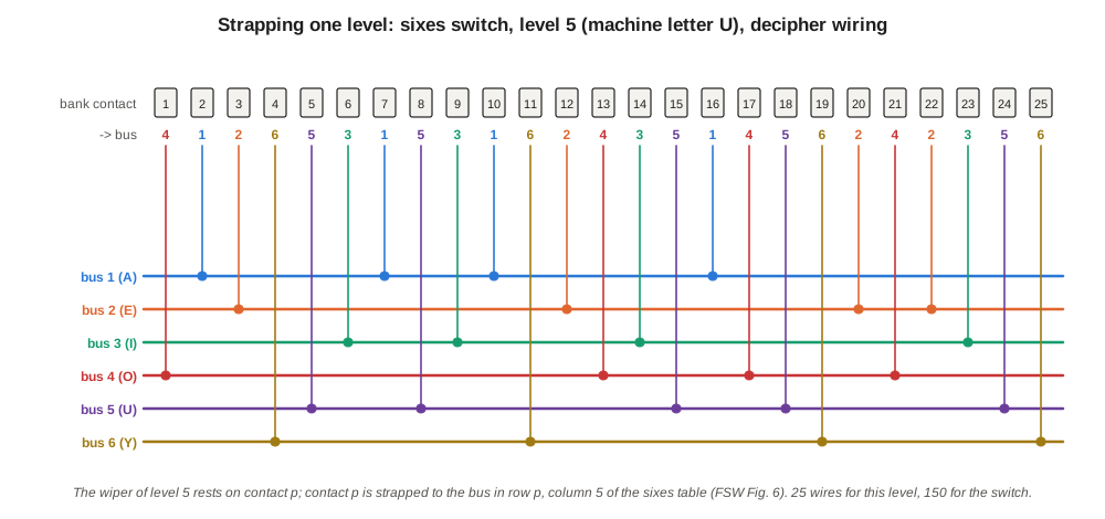
The simulator prints the lists to work from, one line per level:
$ python3 purple_sim.py --wiring sixes
# sixes, decipher wiring: input level L, bank contact P -> output bus O
L1  1:2 2:6 3:1 4:4 5:3 6:2 7:6 8:3 9:5 10:4 11:2 12:5 13:3 14:4 15:1 16:5 17:6 18:2 19:1 20:3 21:6 22:1 23:6 24:4 25:5
L2  1:1 2:3 3:5 4:3 5:6 6:1 7:5 8:6 9:4 10:5 11:1 12:4 13:1 14:2 15:6 16:4 17:2 18:3 19:2 20:1 21:5 22:3 23:4 24:6 25:2
...
$ python3 purple_sim.py --wiring t3
# t3, decipher wiring: input level L, bank contact P -> output bus O
L1  1:7 2:15 3:2 4:16 5:12 6:13 7:4 8:9 9:5 10:11 11:19 12:1 13:3 14:9 15:8 16:18 17:14 18:17 19:10 20:20 21:11 22:16 23:6 24:8 25:13
...
Read the first line as: on level 1, contact 1 goes to bus 2, contact 2 to bus 6, contact 3 to bus 1, and so on. The lists use the switch’s own contact numbering, 1 to 25. Post Office uniselectors number their contacts 0 to 24 (P.O. Telephones 3/2); on those, cipher position 1 is contact 0 and every list entry shifts by one. It does not matter which physical contact is called position 1, provided the same choice is made on every level of every switch and on the sense level.
11.3.2 Method
Twenty buses per stage, each collecting 25 wires from 20 levels across two switches, is the “rat’s nest” of 1940. Three practices keep it tidy and checkable.
- Buses on tag strips, not in the air. Each stage gets a strip of 20 numbered tags (6 for the sixes) behind its two switches. Every strap runs from a bank contact to a tag; the bus is the tag. The inter-stage cable leaves from the same tags.
- Colour by bus. Twenty colours of hook-up wire, one per bus, so that a wrong strap shows as a wrong colour at the tag. The six sixes buses reuse six of them.
- One level at a time, ticked off. Print the wiring list, strap one level (25 wires), tick it, and test it before starting the next (below). A level done and tested is never touched again.
At the 0.2 mm² size a strap is easy to dress; slide a short sleeve over each bank terminal before soldering, since adjacent contacts are a few millimetres apart.
11.3.3 The two switches of a stage
In each twenties stage, switch “a” carries levels for inputs 1–10 and switch “b” inputs 11–20 (Volume 10). Their straps go to the same 20 buses: the bus is a property of the stage, not of the switch. The wiring list for input level L is the same whichever switch carries it.
11.3.4 Between the stages
The stages join bus to wiper. In the deciphering direction:
- the plugboard’s twenty twenties lines (machine letters B to Z, in order) go to the wipers of stage #3, input 1 = B, input 2 = C, … input 20 = Z;
- the 20 buses of stage #3 go to the 20 wipers of stage #2, bus n to input n;
- the 20 buses of #2 go to the 20 wipers of #1;
- the 20 buses of #1 go back to the plugboard’s other side, bus n to machine letter n.
The sixes are simpler: plugboard to wipers, buses back to plugboard. Because every connection conducts both ways, these same wires carry the enciphering direction with no change at all.
11.4 The Line Interface
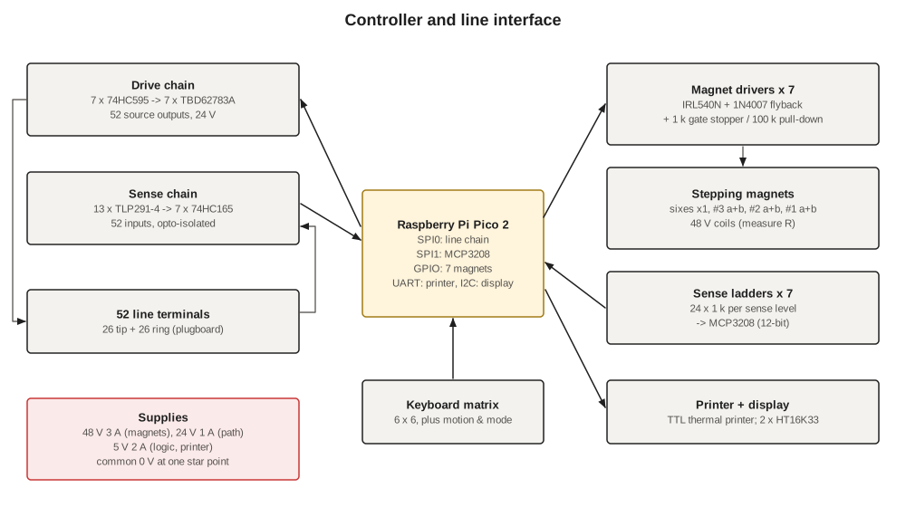
The interface puts current into one plugboard line and reports which line it comes out of. It has 52 lines — the tip and ring of each of the 26 typewriter jacks (Volume 10) — and each line has both a driver and a sensor.
- Drivers. A chain of seven 74HC595 shift registers on one SPI port feeds seven TBD62783A source-driver arrays, eight channels each. A set bit puts 24 V on that line. The TBD62783A is rated 50 V and −500 mA per channel with clamp diodes on every output; the path draws about 10 mA.
- Sensors. Each line also runs to ground through the LED of one channel of a TLP291-4 quad optocoupler in series with 2.2 kΩ, setting about 10 mA from 24 V. The phototransistors feed a chain of seven 74HC165 shift registers read on the same SPI port.
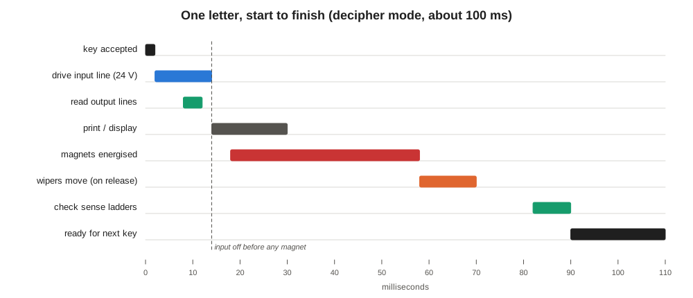
A letter is read like this. In decipher mode, the controller drives the tip line of the pressed key, waits 5 ms for the path to settle, and reads all 52 sensors. Exactly two must be lit: the driven line itself, whose own sensor sees its own 24 V, and one ring line — the output letter. Anything else is a fault and is reported: no ring line lit means a broken path or a wiper between contacts; two lit means a short between straps. In encipher mode the controller drives the ring line and looks for one lit tip line. The drive is then switched off, and only then may any magnet be pulsed: no wiper ever moves while current is flowing, so the contacts never break a live circuit.
11.5 Magnet Drivers
Each of the seven switches has its own magnet driver: an IRL540N logic-level MOSFET, its gate driven from a Pico GPIO through 1 kΩ with a 100 kΩ pull-down so that the magnets stay off while the Pico boots, and a 1N4007 flyback diode across the coil, mounted at the coil. The two switches of a twenties stage have separate drivers, pulsed together, so that either can be stepped alone when re-synchronising after a fault.
Pulse timing comes from the switch data. STC’s uniselector sheet asks for a make of at least 20 ms and a break of at least 10 ms (STC/SASCO p. 564); AE gives 18 ms to operate and 5 ms to release for its Type 45 (AE 1964, Fig. 18). The design uses 40 ms on, then at least 25 ms off before the position is read, generous on both counts. The wipers move during the release, not during the pulse.
11.6 Reading Positions
Every switch has one level given over to reporting its position. Its 25 bank contacts are the taps of a resistor ladder: 24 equal 1 kΩ, 1 % resistors in series, with a 2 kΩ resistor at each end, between 3.3 V and ground. The level’s wiper, through its brush, goes to one channel of an MCP3208 12-bit ADC, with a 1 MΩ resistor to ground. With the wiper on contact p, the ADC sees (p + 1)/28 of 3.3 V: 0.236 V at contact 1, rising 0.118 V — about 146 counts — per position, to 3.06 V at contact 25. With the wiper between contacts, or on a broken wire, the 1 MΩ pulls the input to 0 V, below any valid reading, and the controller reports a fault. On an AE Type 45, the 26th (brush) position reads the same way, which is how the controller knows to give it an extra pulse.
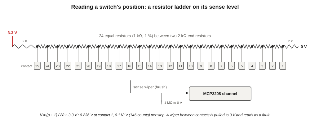
The MCP3208 has eight channels; seven are used, one per switch. The controller reads all seven after every step and converts each reading to a position by rounding. This reading, not the controller’s count, is what the displays show and what the log records.
11.7 The Controller’s Logic
The controller’s job, letter by letter, is short. In outline (MicroPython-style; the real code adds debounce, printing and error recovery):
FAST, MIDDLE, SLOW = motion_selector()          # e.g. motion 4 -> ("t2", "t3", "t1")
STAGE = {"sixes": ["S"], "t1": ["1a", "1b"], "t2": ["2a", "2b"], "t3": ["3a", "3b"]}

def which_twenties_steps(pos):
    # decided from the positions BEFORE anything moves (Volume 4)
    if pos["sixes"] == 24 and pos[MIDDLE] == 25:
        return SLOW
    if pos["sixes"] == 25:
        return MIDDLE
    return FAST

def one_letter(key):
    pos = read_all_positions()                  # from the sense ladders
    check(pos == expected)                      # a missed step stops the machine here
    if key == GARBLE:                           # SPACE: step without enciphering
        out = "-"
    else:
        out = path_lookup(key, mode)            # drive one line, read the far side
    stage = which_twenties_steps(pos)
    pulse(STAGE["sixes"] + STAGE[stage], on_ms=40, off_ms=25)
    expected = advance(pos, stage)              # what the ladders must read next time
    log(n, key, out, pos)                       # n,in,out,sixes,t1,t2,t3
    return out
path_lookup is the only place a letter is produced, and it produces it by sensing which wire the current arrived on; the controller holds no copy of the wiring tables in the switch build. advance adds one to the sixes and to the chosen stage, wrapping 25 to 1, and check compares the next reading with it. On a mismatch the machine stops, prints the position it expected and the one it found, and refuses further letters until the operator re-synchronises: one SET press steps a lagging switch, and the log shows exactly which letter was affected.
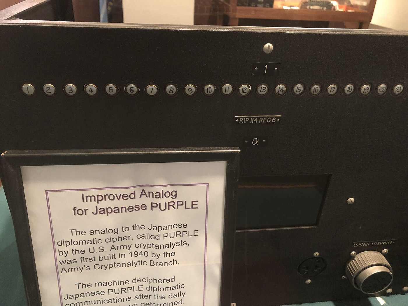
Setting a key. Pressing SET on a switch makes the controller pulse it, one step at a time with the normal timing, until its ladder reads the position entered on the keyboard; holding SET steps it continuously. The 1944 analog had start-position buttons on its panel for the same purpose. With the two switches of a stage stepped together, they always agree; if a ladder shows they do not, the lagging one is stepped alone.
11.7.1 The relay alternative
The SIS analog chose the stepping switch with contacts, and a replica can too. Wire out contacts 24 and 25 of a spare level on the sixes switch and contact 25 of a spare level on each twenties stage. A three-pole, six-way motion switch connects “fast”, “middle” and “slow” to the three stage magnets. The stepping pulse, from a cam or a key contact, goes to the sixes magnet and to the “fast” stage, unless the sixes’ contact 25 is made, which diverts it to “middle”, or the sixes’ contact 24 and the middle stage’s contact 25 are both made, which diverts it to “slow” — two relays and the motion switch. Because the contacts are read while the wipers stand still, before the pulse, the “latched” condition of Volume 4 comes for free. This is close to how the 1940 machine worked; it gives up the controller’s missed-step detection, its logging and its quick key-setting.
11.8 Bringing It Up
The machine is brought up in stages, each tested before the next is built on it. If the all-electronic fallback (Volume 10) was built first, each switch stage replaces its simulated counterpart in turn, and every test below can compare the real stage against the simulated one.
11.8.1 Each switch alone
Before any strapping, mount each switch, wire its magnet driver and its sense ladder, and step it 625 times — 25 full cycles — while the controller logs the ladder after each step. Every reading must be the previous one plus one, wrapping 25 to 1. Any repeat is a missed step; any jump of two is a double step. Clean, adjust and lubricate until 625 steps run clean three times, then try 625 at ten steps a second. A switch that cannot do this will not do it later.
11.8.2 Each level as it is strapped
After strapping a level, step the switch to each position in turn and check continuity from the level’s wiper to the bus the list names. The controller can do this automatically if the stage is temporarily wired with its buses to the sense chain: drive the wiper’s line, step through 25 positions, and compare the lit bus with the list. Twenty-five probes test the level’s 25 straps.
11.8.3 Each stage in the machine: the sweep
With the whole path connected and the plugboard plugged straight through (cord A to A, B to B and so on), hold three switches still and step the fourth through all 25 positions, measuring the complete 26-letter alphabet at each. The controller measures an alphabet by driving each of the 26 input lines in turn. The simulator gives what each alphabet must be:
$ python3 purple_sim.py -k 1-1,1,1-12 --sweep t3
t3     in : AEIOUYBCDFGHJKLMNPQRSTVWXZ
1         : EAIUOYRWKHCSJZDPVTXLMBGNFQ
2         : EAIUOYFVNQPTXHSWLMJRKCDZBG
3         : EAIUOYQKCPSWMJLNZFTHRDBXGV
4         : EAIUOYDHPLMCZWBQGXNKJSFVTR
...
Read the first row as: with every switch at 1 and #3 at 1, typing machine letter A prints E, E prints A, I prints I, B prints R, and so on. The six sixes letters do not change down the column, because only #3 moves. Because the other two twenties stages hold one fixed permutation throughout the sweep, every one of #3’s 500 straps is exercised once, and any wrong strap shows as a wrong letter in a row whose position and input identify it. Four sweeps (--sweep sixes, t1, t2, t3), 100 alphabets in all, test all 1,650 straps.
11.8.4 Stepping
With a straight plugboard, set the key 21-1,25,5 and motion 123 and press the garble key eight times. The display and log must follow Volume 4’s stepping figure, which the simulator prints:
$ python3 purple_sim.py -k 21-1,25,5-12 --steps 7
letter  sixes  #1  #2  #3   next to step
     1     21   1  25   5   sixes + #1 (fast)
     2     22   2  25   5   sixes + #1 (fast)
     3     23   3  25   5   sixes + #1 (fast)
     4     24   4  25   5   sixes + #3 (SLOW)
     5     25   4  25   6   sixes + #2 (middle)
     6      1   4   1   6   sixes + #1 (fast)
     7      2   5   1   6   sixes + #1 (fast)
Repeat for all six motions, and run one long test of 15,625 garbles from 1-1,1,1 to confirm that the machine comes back to 1-1,1,1 after exactly one period, and not before. At ten letters a second that takes 26 minutes, and it exercises every switch through every position many times.
11.9 Verification Against the Simulator
11.9.1 The log
The controller logs one line per letter: letter number, input, output, and the positions of the four switches before the letter, read from the ladders. The simulator writes the same format:
$ python3 purple_sim.py -k 9-1,24,6-23 -a NOKTYUXEQLHBRMPDICJASVWGZF -d ZTXODNWKCCMAVNZXYWEE --log
n,in,out,sixes,t1,t2,t3
1,Z,F,9,1,24,6
2,T,O,10,1,25,6
3,X,V,11,1,1,6
...
17,Y,U,25,1,15,6
18,W,I,1,1,15,7
19,E,M,2,1,16,7
20,E,I,3,1,17,7
Line 17 shows the middle switch (#3) about to step, and line 18 the result: #3 has gone from 6 to 7 and #2, the fast switch, held at 15 for one letter. A machine log and a simulator log for the same key and text are compared with diff; any line that differs gives the letter, the input and both switches’ positions at the moment the machine went wrong.
11.9.2 Acceptance test: Part 1 of the 14-part message
The acceptance test is the message the machine is famous for. Set the key of Volume 12 — switches 9-1,24,6, motion 4 (23), alphabet NOKTYUXEQLHBRMPDICJASVWGZF — and type the 1,285 transcribed letters of Part 1, using the garble key for each of the 28 letters the intercept operator marked as uncertain or the archive copy leaves unreadable. Compare the log with:
$ python3 purple_sim.py -k 9-1,24,6-23 -a NOKTYUXEQLHBRMPDICJASVWGZF -d PART1 --log(PART1 selects the transcript built into the simulator.) The machine passes if every line agrees. The printed plaintext must begin FOVTA TAKID ASINI MUIMI, as Weierud’s notes on the message say it does (CryptoCellar), and must reach, at letter 105, THEGOVE-NMENTOFJAPANLFLPROMPTEDBYAGENUINEDESIRE — the English of the note handed to Secretary Hull on 7 December 1941 (Volumes 7 and 12). Three further checks complete acceptance:
- Encipher reproduces the intercept. In encipher mode, typing the plaintext (with X for each garble) must reproduce every legible letter of the intercepted ciphertext — the simulator’s check 11.
- Round trips in all six motions. For six random keys, one per motion, encipher 500 random letters and decipher them again.
- Appendix E position check. From key 13-25,23,12, motion 321 (32), 200 garbles must leave the machine at 13-1,6,3, the position Freeman, Sullivan and Weierud give for group 41 of their second test message (FSW, p. 38).
11.10 The Fallback’s Verification
The all-electronic fallback runs the same tests with a different meaning. Its substitution comes from the tables in its firmware, which are the simulator’s own; the self-test of purple_sim.py runs on the Pico at power-up and must print 15/15 before the machine accepts a key. The sweeps then test not the strapping but the plugboard, the line interface and the cords, and the Part 1 acceptance run tests the whole chain from keyboard to printer. When the switch stack later replaces the firmware stage by stage, the same tests, run again, are the proof that each stage is right.
Next — Volume 12: Running PURPLE — Keys, Procedures and a Message Worked in Full. How a Japanese code clerk keyed the machine in December 1941, how the Americans read the same keys, and Part 1 of the 14-part message deciphered from indicator to plaintext — then a new message enciphered the 1941 way.
Comments (0)