PURPLE · Volume 10
PURPLE — Volume 10 — Building a PURPLE — Design
No kit exists, so this is a design: seven telephone uniselectors, a two-conductor plugboard, a small controller that only decides which magnet to pulse, and a fallback that needs no switches at all
10.1 About This Volume
This is the first of three build volumes. There is no PURPLE kit and, unlike the Enigma or the Apollo DSKY, no open-source reproduction to buy, so the build is a design of its own: a working PURPLE analog that enciphers and deciphers with real electromechanical stepping switches, set from the same keys the Japanese used, and checked letter for letter against the published decipherment of the 14-part message of December 1941.
The design follows the SIS analog in everything that matters cryptographically. A sixes switch and three twenties stages of 25-point telephone stepping switches carry the letters; plugboards on either side set the daily alphabet; the stepping rule of Volume 4 decides which switch moves. Two things are modern. A small microcontroller does what the second section of the SIS sixes switch did — reading positions and choosing which magnet to pulse — and it also scans the keyboard, drives a printer and keeps a log. And every switch carries one extra level whose only job is to report where the switch actually is, so that a missed step is caught at once instead of turning the rest of a message into nonsense.
The volume covers the requirements, the history the design draws on, the choice of stepping switch (with real types and their published data), the architecture, the allocation of switch levels, the plugboard, the keyboard and printer, power, the all-electronic fallback, a bill of materials, and layout and safety. Volume 11 covers the wiring, the controller logic and verification against the simulator; Volume 12 covers operating it.
None of this has been built yet. Everything here is a design and a procedure. Where the account of the actual build will go, the text carries a marker.
10.2 What the Replica Has to Do
The requirements fall out of Volume 4.
- Encipher exactly as PURPLE did. For any key — four starting positions, one of six motions, a 26-letter alphabet — the machine must produce the same letters as the simulator,
03-outputs/tools/purple_sim.py, which in turn reproduces the published decipherment of Part 1 of the 14-part message letter for letter (Volume 11). That is the acceptance test. - Do the enciphering in the switches. The cryptographic path — plugboard, sixes switch, three twenties switches, plugboard — must be a continuous electrical path through real wipers and bank contacts, as in 1940. Nothing digital may compute a substitution.
- Run both ways. Decipher mode feeds the twenties stages from #3 to #1; encipher mode feeds them from #1 to #3, so that the wires apply their inverse. The analog did this by swapping typewriters; the replica does it with a switch.
- Step by the rule. The sixes switch steps after every letter, and exactly one twenties stage steps with it, chosen from the positions before stepping: slow if the sixes stands at 24 and the middle at 25, middle if the sixes stands at 25, fast otherwise.
- Take a key quickly. Setting four starting positions and a motion must take a minute, not a screwdriver; the 1944 improved analog had buttons for exactly this.
- Know where it is. Every switch’s position must be readable at all times and compared with what it should be. A stepping switch that misses one step silently corrupts everything after it; the machine must notice.
- Print and log. Output goes to paper, grouped in fives, and to a log that can be compared with the simulator line by line.
10.3 What the SIS Built
The design draws on two American machines. The first analog, built in 1940 and now known as PURPLE Analog No. 1, used commercial six-level, 25-point telephone switches: one for the sixes, a second six-level section moving with it to control the stepping and the position lamps, and four six-level switches moving as one for each twenties stage — thirteen or fourteen switches in all, depending on whether the sixes’ control section is counted separately (FSW, p. 5; CQ 1984–85, p. 71). It had one physical plugboard with double-contact jacks serving as both input and output plugboard, which works because the Japanese plugged both identically (FSW, p. 3).
The second is the improved analog of 1944 on display at Fort Meade (Volume 6 shows it). Its front panel carries position lamps, a central plugboard, the six-position stepping-order knob shown in Volume 4 and buttons for setting the switches’ starting positions. English-language descriptions say it carried each stage’s levels on a single shaft and added a level that set the starting positions automatically (Wikipedia, “Type B Cipher Machine”); no primary description of its circuit was found, and the design here does not depend on one. The design here is closest in spirit to the 1944 machine: fewer, larger switches; set-up buttons; and a position indication on every switch.
10.4 Choosing Stepping Switches
10.4.1 What a PURPLE switch must be
The cipher constrains the switch tightly.
- Exactly 25 positions in an endless cycle. Position 25 must step to position 1 with one pulse, as a double-ended wiper on a half-ring bank does. A switch with a 26th “home” or brush position can be used, but only by stepping through the extra position with an extra pulse each time round.
- Enough levels. The sixes need 6 cipher levels; each twenties stage needs 20. One more level per switch is wanted for position sensing.
- Non-bridging wipers on the cipher levels. A bridging wiper touches the next contact before leaving the last; a non-bridging one breaks first. Bridging wipers would momentarily join two contacts — two cipher outputs — as the switch steps. Automatic Electric’s handbook defines the two and the reason for choosing between them: non-bridging wipers have “shorter tips that leave one bank contact before engaging the next, avoiding the electrical interconnection between circuits of adjoining bank contacts” (AE, How to Use Rotary Stepping Switches, 1964, p. 5). Because the controller never steps a switch while current is flowing in the cipher path (Volume 11), bridging wipers would in fact work, but non-bridging ones remove the question.
- Pulse-driven, at a modest rate. Every telephone stepping switch of this family can be stepped by external pulses. The replica needs no more than about ten letters a second.
10.4.2 Types that fit
Three families of telephone switch meet these requirements, and surplus examples of all of them turn up.
British Post Office uniselectors (Nos. 2 and 3) and their STC equivalents. The standard British uniselector has a bank of 25 contacts per level, with the wipers double-ended so that the switch gives “two appearances of 25 points per revolution”. STC’s catalogue sheet for its types 4150 and 4160, which it describes as equivalent to the Post Office Nos. 2 (heavy duty) and 3 (light duty), lists versions with 3, 4, 5, 6, 8, 10 or 12 levels; bridging or non-bridging wipers; contacts rated 0.5 A at 50 V; impulse drive with a minimum make of 20 ms and break of 10 ms, to a maximum of 80 revolutions a minute; and a life of 500,000 revolutions (light duty) or 2,000,000 (heavy duty) (STC/SASCO data sheet, p. 564). The Post Office’s own training pamphlet numbers the contacts 0 to 24 and calls the mechanism “reverse action”: the wipers move when the magnet releases (P.O. Telephones 3/2). Post Office exchanges used them in huge numbers until the 1990s, which is why they are the most common surplus 25-point switch today. Coil voltage was nominally 50 V in exchange use; the coil resistance of any particular unit should be measured, since several windings were made.
Automatic Electric Type 13. AE’s 1961 bulletin describes the Type 13 as “arranged for 25-point operation”, with wiper tips 180° apart so that each contact is traversed twice per revolution, one to six levels, indirect drive (the wipers advance as the armature restores), 30 steps a second from external pulses and 50 self-interrupted, and standard coils for 6 to 110 V. The 48-volt coil is 100 Ω (AE Technical Bulletin 961-473, §8 and Table I). A six-level 25-point switch is what the SIS used; a PURPLE built from Type 13s follows the 1940 layout exactly.
Automatic Electric Type 45. The larger AE switch has 25 bank contacts per level “and one wiper brush terminal contact”, up to 16 levels, bridging or non-bridging wipers, about 35 steps a second from external pulses, and the same 100 Ω coil at 48 V. But “there are 26 steps to each half revolution”: the 26th step parks the wipers on the brush position (AE TB 961-473, §11). AE’s own handbook shows the cure, in a scanning circuit where “Position 26 on the Type 45 stepping switch is absorbed in each half rotation, so that 25 points are sequentially scanned” (AE 1964, “Scanning Circuit”). The replica’s controller can absorb it the same way, with an extra pulse whenever a switch reaches 26. The measured operate and release times — 18 ms and 5 ms — and a maximum of about 43 pulses a second leave ample margin (AE 1964, Fig. 18).
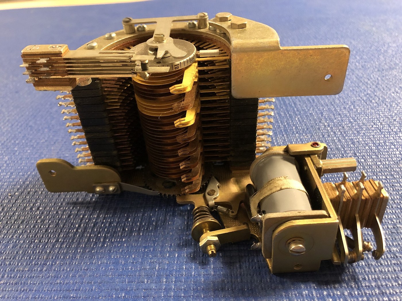
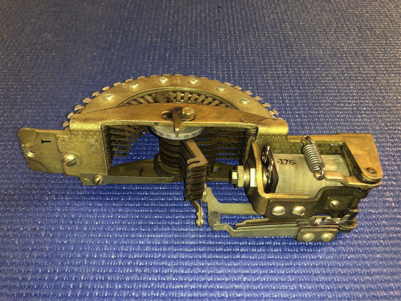
Bell System switches of the same pattern exist too. The Telephone Museum in Waltham displays a Western Electric 206A “with 6 layers and 25 positions” (Commons); no published data sheet for it was found, so its electrical details would have to be measured.

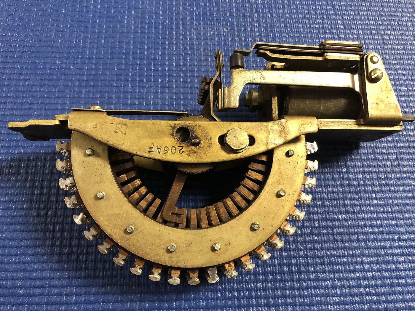
Table 1 — Types that fit
| Type | Points | Levels | Wipers | Step on | Pulse rate | 48–50 V coil | Fit for PURPLE |
|---|---|---|---|---|---|---|---|
| P.O. No. 2 / 3; STC 4150 / 4160 | 25, double-ended | 3–12 | bridging or non-bridging | release | make ≥ 20 ms, break ≥ 10 ms (≤ 33 pulses/s) | 50 V nominal; measure R | primary choice |
| AE Type 13 | 25, double-ended | 1–6 | per order | release | 30 steps/s | 100 Ω | SIS layout (14 switches) |
| AE Type 45 | 25 + 1 brush position | up to 16 | bridging or non-bridging | release | ~35 steps/s | 100 Ω | needs the 26th step absorbed |
| WE 206A | 25 | 6 (museum label) | not known | not known | not known | not known | measure before buying many |
Sources: STC/SASCO data sheet p. 564; AE Technical Bulletin 961-473 (1961) §§8, 11 and Table I; AE “How to Use Rotary Stepping Switches” (1964) Fig. 18; Telephone Museum label via Commons. STC gives a maximum of 80 rpm in impulse drive; its minimum make and break times limit external pulsing to about 33 pulses a second, three times what the replica needs.
10.4.3 Buying surplus switches
There is no new production. Uniselectors, AE rotaries and their relatives circulate among telephone collectors and on auction sites; as of October 2026 no listing could be verified by search for this volume, so prices are not given. AE’s 1964 handbook quoted about $45 for a twelve-level, 25-point switch new (AE 1964, “Economy”).
What to check before buying, and on arrival:
- Count the levels and the points. A 25-point bank with a double-ended wiper; the number of levels needed (8 for the sixes, 12 for each twenties switch in the primary design).
- Look at the wiper tips. Short tips are non-bridging, long flat tips bridging. Mixed assemblies exist.
- Read the coil. Coils usually carry a code and resistance. Measure the resistance; a coil reading open or far below its marking is burned out.
- Step it by hand. With the armature pressed and released by hand, the wipers must advance cleanly one contact at a time, all the way round, with no rubbing between levels.
- Look for corrosion and old lubricant. Gummed oil on the ratchet causes missed steps. Cleaning and relubrication follow AE’s or the Post Office’s instructions; the Telephones section of this site covers them (Telephone Switching History, Volume 8).
- Buy spares. One spare 12-level switch covers a failure in any stage.
10.5 Architecture
The machine has five parts: the switch stack, the plugboard, a line interface, a controller and the operating panel.
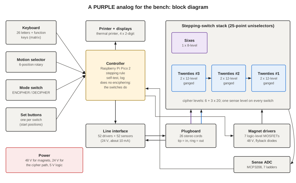
The switch stack holds seven 25-point uniselectors: one 8-level switch for the sixes, and two 12-level switches for each of the three twenties stages. The two switches of a stage are pulsed together and wired as one 24-level switch; they behave exactly as the four six-level switches of a 1940 stage did.
The plugboard sets the daily alphabet for both directions at once (below).
The line interface puts a small current into the cipher path at one end and looks for it at the other. It has a driver and a sensor on every one of the 52 plugboard lines — 26 on the input side and 26 on the output side — so that the same hardware can run the path in either direction. When a key is pressed in decipher mode, the controller switches 24 V onto that key’s input line; the current runs through the plugboard, the switch wipers and the strapping, back through the plugboard, and lights the optocoupler on exactly one output line. That line is the output letter. In encipher mode the roles of the two sides swap.
The controller is a Raspberry Pi Pico 2 — “available now from $5”, with three ADC inputs and twelve PIO state machines (raspberrypi.com, read October 2026). It scans the keyboard, operates the line interface, prints, and after each letter decides from the switch positions which stage steps, then pulses the magnets. It never computes a substitution: if the strapping is wrong, the machine prints a wrong letter, exactly as a mis-wired 1940 analog would. It does, however, check its own work, by reading every switch’s sense level after every step and comparing the reading with the position it expects.
The operating panel carries the keyboard, a six-position motion selector engraved with the six motions as on the 1944 analog, an ENCIPHER/DECIPHER switch, a set button and a two-digit position display for each of the four switches, and a thermal printer.
10.5.1 Why a controller at all
The SIS analog had no computer. Its stepping logic was a few contacts on the sixes switch’s second section, and a faithful relay version is possible here too (Volume 11 sketches it). The controller earns its place in three ways. It makes key-setting fast: pressing SET on a switch steps it until its sense level reads the wanted position. It catches missed steps, which in a relay machine show up only as garbled plaintext forty letters later. And it logs every letter with the positions it was enciphered at, which is what makes a line-by-line comparison with the simulator possible.
10.6 Allocating the Levels
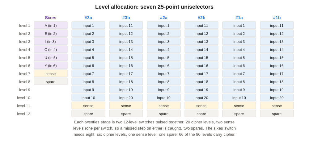
Each twenties stage gets two sense levels, one per switch, because the two switches of a stage are separate mechanisms. If one of them misses a step, the stage’s 20 levels are no longer in the same position, and only a sense level on each can show it. With 12-level uniselectors this leaves one spare level on every switch, useful for repairs: a level with a damaged contact can be moved to the spare.
Alternative: the 1940 layout. With six-level switches such as the AE Type 13 or WE 206A, the stack becomes fourteen switches: two for the sixes (cipher plus sense and control) and four for each twenties stage (24 levels: 20 cipher, four sense). Nothing else in the design changes; the controller simply pulses four magnets per stage instead of two, and reads more sense levels.
Alternative: AE Type 45. Two 12- or 16-level Type 45s per stage work the same way, with the controller adding one extra pulse whenever a switch’s sense level reads the 26th (brush) position, where no bank contact is touched.
10.7 The Plugboard
The 1940 analog’s single plugboard with double-contact jacks is the right idea, and modern audio parts make it easy. The board has two rows of 26 three-pole (TRS) jacks.
- The typewriter row is labelled A–Z. Each jack’s tip is the keyboard line for that letter in decipher mode, and its ring is the printer line.
- The machine row is labelled in machine order, A E I O U Y and then B C D F … Z. Each jack’s tip goes to the switch end that receives the input in decipher mode — a sixes wiper or a twenties #3 wiper — and its ring goes to the other end: a sixes output bus or a twenties #1 output bus.
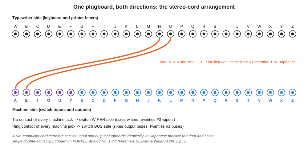
A two-conductor cord from typewriter jack N to machine jack A therefore connects keyboard N to the sixes wiper A and sixes output bus A to printer N: one cord sets both plugboards, and they cannot disagree. Setting a daily alphabet means plugging 26 cords, reading the alphabet straight across in machine order (Volume 12). Shielding is unnecessary; the path carries ten milliamps of direct current.
Two practical details matter. Use jacks whose tip and ring springs are both switched off when no plug is present, or no switching at all, so that an empty jack leaves its line open rather than shorting it. And colour the six sixes jacks differently from the twenty twenties jacks, as the illustrations in this series do: a cord plugged into the wrong group is the commonest setting error, and the machine cannot detect it.
10.8 Keyboard, Printer and Panel
Keyboard. The Japanese and American machines used electric typewriters. A replica can use any keyboard that reports 26 letters reliably. A custom matrix of 26 mechanical keyswitches plus a few function keys (SPACE for garbles, SET, RESET, LINE FEED) is simplest and gives the controller full control of debounce; an old typewriter keyboard fitted with switches is the more evocative choice.
Printer. A 58 mm thermal receipt printer with a TTL serial input needs only a UART pin. Adafruit’s Mini and Tiny thermal printers, the usual hobby choice, were both marked “No longer stocked” on adafruit.com when checked in October 2026 (Mini, Tiny); generic modules using the same command set remain on sale elsewhere. A vintage teleprinter is the faithful alternative and the subject of its own project.
Displays and controls. Four two-digit seven-segment displays on HT16K33 driver backpacks show the sixes and the three twenties positions, read from the sense levels rather than from the controller’s memory, so that they show what the switches are actually doing. The motion selector is a single-pole six-way rotary switch with a resistor on each position, read by one of the Pico’s ADC inputs. The ENCIPHER/DECIPHER switch is a plain toggle read by a GPIO pin; because the line interface can drive either side, nothing in the cipher path is switched.
10.9 Power
Three supplies, with their returns joined at one point:
- 48 V for the magnets. A 100 Ω coil at 48 V draws 0.48 A. Each letter steps the sixes switch and both switches of one twenties stage — three magnets at once, about 1.5 A for 40 ms. A 48 V, 3.3 A supply (for example Mean Well’s LRS-150-48) has ample headroom for setting several switches together. Uniselectors with lower-resistance coils draw more; measure first and size accordingly.
- 24 V for the cipher path. The path current is set by a resistor at each sensor to about 10 mA. Telephone contacts of nickel silver are designed for exchange voltages and benefit from a wetting current; 24 V at 10 mA is a conservative choice well inside STC’s 0.5 A, 50 V contact rating.
- 5 V for logic and printer. Thermal printers draw over 1.5 A while printing; a 5 V, 3 A supply covers the printer, the Pico and the logic.
Every magnet coil gets a flyback diode, and the 48 V wiring is kept apart from the logic wiring. Volume 11 gives the driver circuit.
10.10 The All-Electronic Fallback
A stepping-switch machine depends on surplus parts that may take months to find. The design has a fallback that keeps everything except the switches: the same panel, keyboard, plugboard, printer and displays, with the switch stack replaced by the Pico computing the substitution from the published tables.
In the fallback, the machine row of the plugboard is wired to a second line interface — 26 sensors on the tip contacts and 26 drivers on the ring contacts, the same parts again — instead of to the switch stack. When a key is pressed, the controller sees which machine-row jack the keyboard current reaches through the cords, computes the switch permutation from the published tables, and drives the resulting machine-row ring line, so that the cords carry the answer back to the printer line. The cords therefore still do the plugboard’s work physically, and the motion selector, set buttons and displays behave as before. The code is a direct port of purple_sim.py’s Purple class, which is plain Python with no dependencies and runs under MicroPython; its fifteen self-tests run on the Pico itself.
The fallback is also how the switch build should start. Built first, it gives a working panel, a tested line interface and a tested controller, and it becomes the reference against which each switch stage is brought up: the stack replaces the simulated stages one at a time (Volume 11).
10.11 Bill of Materials
Quantities are for the primary design. Prices are not given for surplus switches, which have no list price; catalogue parts are standard and widely stocked.
Table 2 — Bill of Materials
| Item | Part | Qty | Notes |
|---|---|---|---|
| Sixes switch | 25-point uniselector, 8 levels, non-bridging | 1 | P.O. No. 2/3 or STC 4150/4160 pattern |
| Twenties switches | 25-point uniselector, 12 levels, non-bridging | 6 | two per stage; plus 1 spare |
| Controller | Raspberry Pi Pico 2 | 1 | MicroPython or C |
| Line drivers | 74HC595 shift register + TBD62783A 8-channel source driver | 7 + 7 | 52 lines; TBD62783A rated 50 V, −500 mA per channel |
| Line sensors | TLP291-4 quad optocoupler + 74HC165 shift register | 13 + 7 | 52 lines; 2.2 kΩ series resistor per line |
| Magnet drivers | IRL540N logic-level MOSFET, 1N4007 diode | 7 + 7 | one per switch; 1 kΩ gate, 100 kΩ pull-down |
| Position sense | MCP3208 8-channel 12-bit ADC; 1 kΩ 1 % resistors | 1; 7 × 24 + 14 × 2 kΩ | one ladder per switch (Volume 11) |
| Plugboard | TRS panel jacks; two-conductor patch cords | 52; 26 | sixes jacks in a different colour |
| Keyboard | mechanical keyswitches + keycaps | ~32 | 26 letters + function keys |
| Motion selector | 1-pole 6-way rotary switch + 6 resistors | 1 | engraved 123 … 321 |
| Mode switch, set buttons | toggle; momentary buttons | 1; 4 | |
| Displays | 2-digit 7-segment + HT16K33 backpack | 4 | or 2 × 4-digit |
| Printer | 58 mm TTL thermal printer | 1 | 5–9 V, 1.5 A peak |
| Power | 48 V 3.3 A; 24 V 1.5 A; 5 V 3 A supplies | 1 each | e.g. Mean Well LRS-150-48, LRS-35-24, LRS-15-5 |
| Wiring | 0.2 mm² stranded hook-up wire in 20 colours; tag strips | ~2,000 joints | the strapping (Volume 11) |
| Enclosure | wooden or steel case, switch rack, front panel | 1 |
The TBD62783A in DIP (APG suffix) is listed as no longer manufactured by at least one distributor; the surface-mount AFG version on an adapter, or a discrete high-side switch per line, are substitutes.
10.12 Layout and Safety
The switch stack is the heavy part. Seven uniselectors mount on a vertical rack, wipers facing the front so that the moving parts can be watched through a window, with the strapping fanned out behind on tag strips. A stage’s two switches sit side by side; the stages run left to right in the deciphering order #3, #2, #1, which keeps the inter-stage cables short and makes the signal path readable from the front, as in the SIS schematic. The electronics sit on a separate board at the bottom of the rack, away from the magnet wiring.
Three hazards need care.
- Stored energy in coils. A magnet switched off without a diode produces a spike of hundreds of volts. Every coil has its diode at the coil, not at the driver board.
- 48 V on open contacts. 48 V DC is not usually dangerous to touch, but it is enough to arc on dirty contacts and to destroy logic parts if shorted to them. The magnet supply has its own fuse, and nothing at 48 V runs on the plugboard.
- Pinch points. A stepping switch’s ratchet and armature move fast and hard. The rack is enclosed, and the window is clear plastic, not open.
Next — Volume 11: Building a PURPLE — Wiring, Controller and Verification. Strapping 1,650 contacts from the wiring tables, the line interface and magnet drivers, the position-sense ladders, the controller’s logic, and the test that proves the finished machine deciphers the Pearl Harbor message exactly as the simulator does.
Comments (0)