DSKY · Volume 19
DSKY — Volume 19 — My Open DSKY: The Build
A grey-and-black printed panel on my electronics bench, and the moment every lamp lit at once
19.1 About This Volume
Volume 18 described the Open DSKY in general: S&T GeoTronics’ kit, its parts and its software. This volume is about one particular Open DSKY, the one I built. It sits on my electronics bench on a printed stand, between bench power supplies and meters, and when I switch it on, the lamp field and the green registers go through the same self-test the original’s crews watched for before they trusted the panel.
What follows is a tour of the unit as it stands: the housing and how its colours follow S&T’s print scheme, what is behind the bezel, how it is powered, the two NASA-style plates on its side, and what the first lamp test and the idle panel actually show. Where the firmware explains what is on the display, the explanation comes from the source code of Bill Walker’s software, which S&T has shipped on every new unit since January 2020.
The next two volumes carry on from here. Volume 20 is the printed command manual I run the unit from, and Volume 21 is the launch and landing programs and the changes I have made to the code.
19.2 The Kit
S&T sold the Open DSKY at several levels of completeness, from a bare PCB to fully assembled units, and the Complete kits include the printed case. The kit arrives as boards, displays, lamps, keycaps, modules and printed housing parts, with the Instructable “Open Apollo Guidance Computer DSKY” as the assembly guide. A kit bought since January 2020 also brings Walker’s firmware pre-loaded on the Nano, his audio clips on a micro-SD card, and a printed copy of his Apollo Open DSKY Command Reference, the manual that is the subject of Volume 20. My copy of that manual is printed and bound with two rings.
19.3 The Housing
The case is the part of the Open DSKY that does the most to make it read as Apollo hardware, and it is all 3D-printed. S&T’s Instructable divides it into five parts (the Bezel, Top Plate, Mid Ring, Bottom and Battery Box Lid) and says S&T prints “the Bezel, Top Plate and Mid Ring on Grey material, while the Bottom and Battery Door are printed in Black.” Mine follows that scheme exactly: a light-grey front with a fine metallic fleck in the filament, and a dark, almost black, rear section behind it.
The grey front is in two framed halves above the keypad. The left frame holds the fourteen lamp windows, two columns of seven with printed legends; the right frame holds the display window, a frosted panel with the green PROG, VERB and NOUN legend blocks, the COMP ACTY legend, and the three thin horizontal rules that divide the five-digit registers on the original. Below them, the keypad is a separate grey plate with nineteen black keycaps. Small screws at the corners of each frame hold the stack together, which is also how the original’s bezel was fastened, and it is a large part of why the replica looks like a manufactured instrument rather than a printed toy.
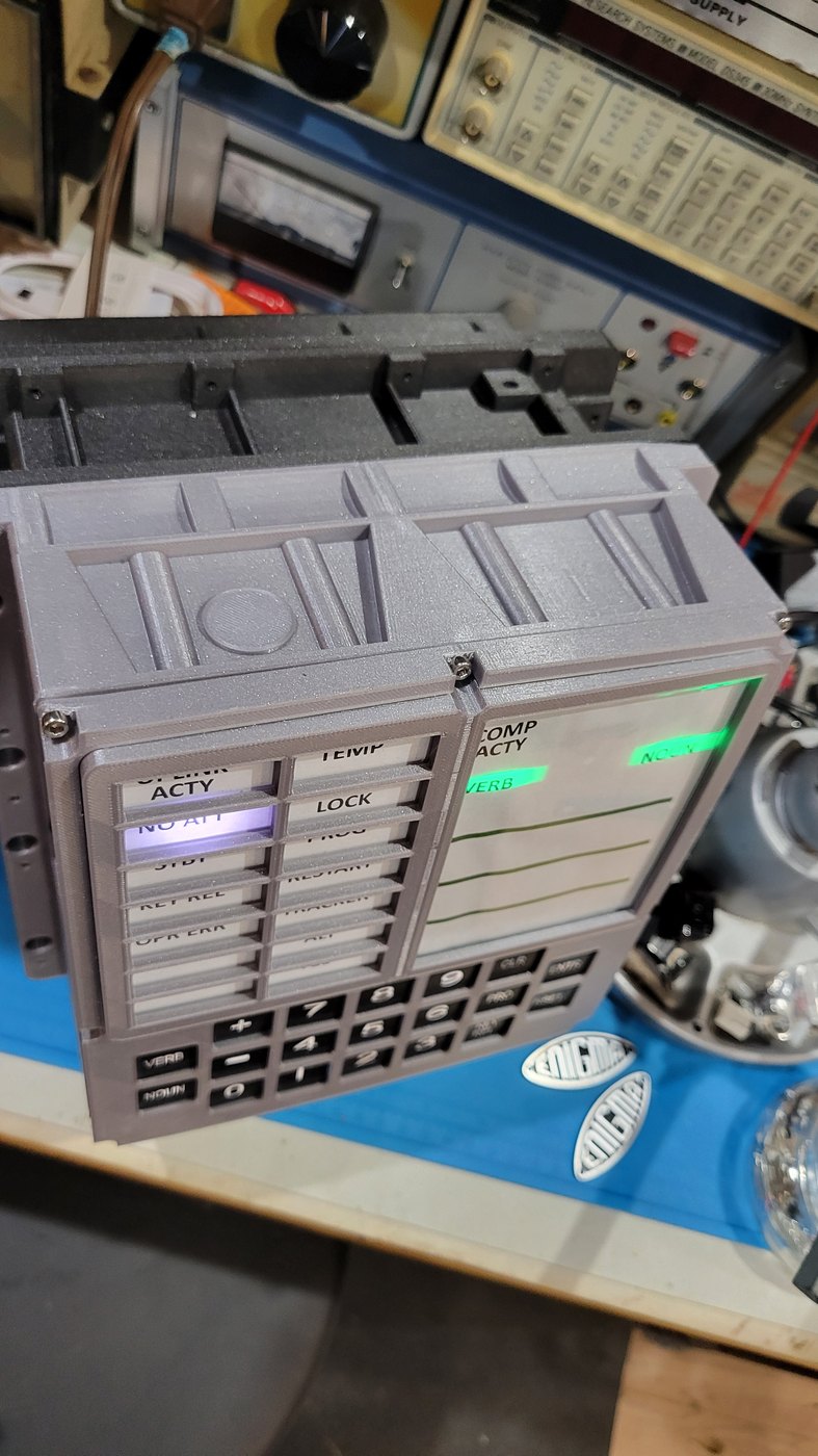
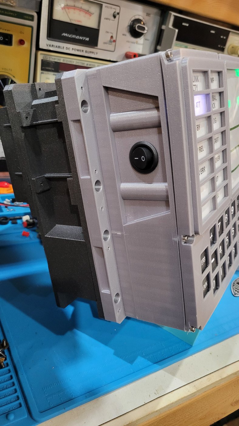
Seen from above (Figure 3), the top of the grey body carries the ribs and recesses of the original’s casting, and behind it sits the black rear frame, a deep open structure with mounting bosses and slots along its edges. The real DSKY was a box that slid into the spacecraft’s instrument panel, and the black frame reproduces that rear mounting.
S&T offers two bodies. The standard Slim is the panel and a shallow case. The BigBack, offered from April 2018, adds the deep rear housing of the original for a full 1:1 replica and takes S&T about forty hours to print (S&T BackerKit update, 20 April 2018). The depth of the black rear section is what tells the two apart; a side view against a ruler settles it.
The unit stands on a teal printed block on my bench, which tilts it slightly back and lifts the keypad.
19.4 Behind the Bezel
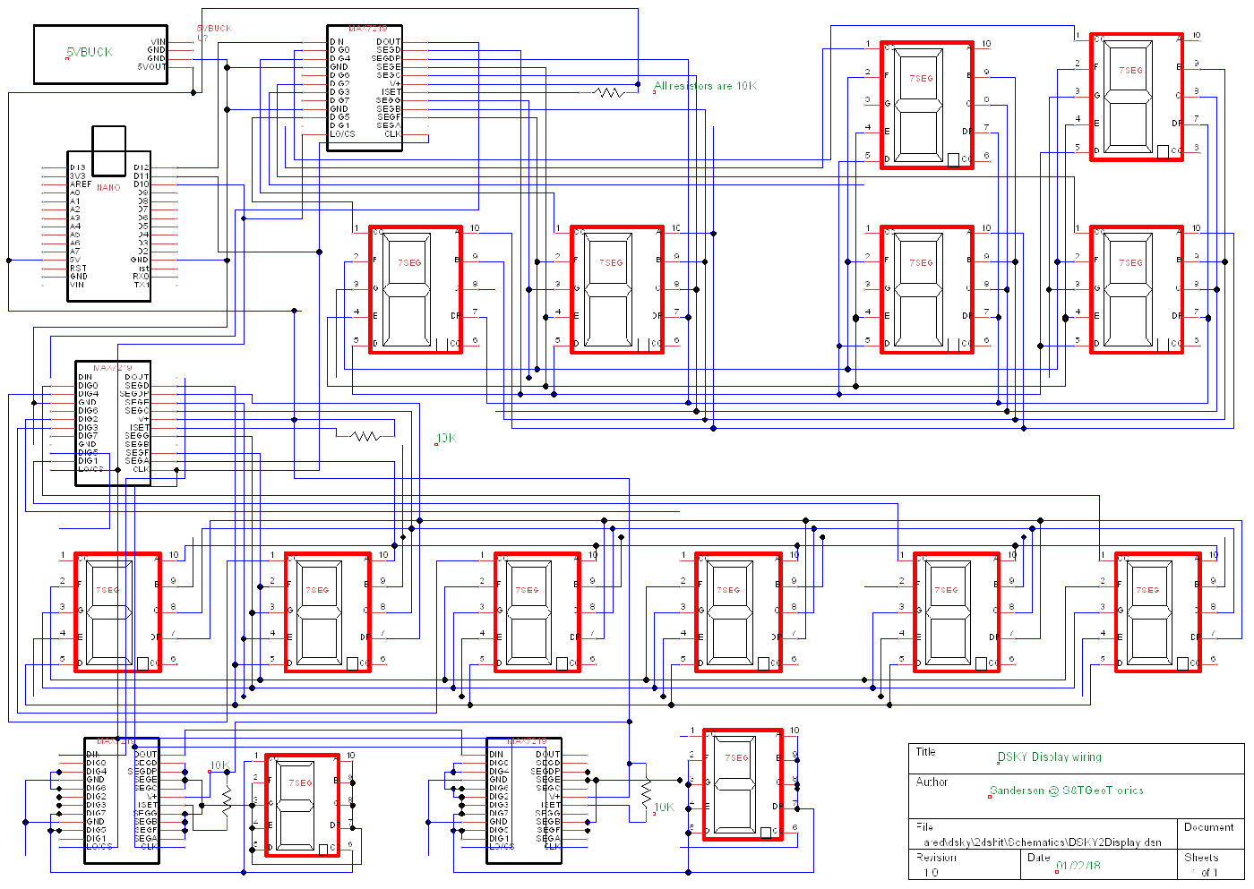
The case hides a fairly dense board. S&T’s schematics, published with the Instructable, show four groups of parts.
The brain. An Arduino Nano (ATmega328P) plugs into the main board. Walker’s firmware, CustomDSKY.ino, is about 3,000 lines of C++. The board has only 2 KB of RAM, which is why the firmware is written as a long list of fixed functions rather than anything like an emulator.
The displays. Four MAX7219 driver chips each run up to eight seven-segment digits over a shared three-wire serial bus (the firmware drives it from pins 10, 11 and 12). The first chip handles the PROG, VERB and NOUN digits; the other three handle the three five-digit registers and their sign digits. Every digit on the panel is addressed in the code as a chip number and a digit position, which matters in Volume 21, where the landing simulation writes altitude and descent rate into the second and third registers.
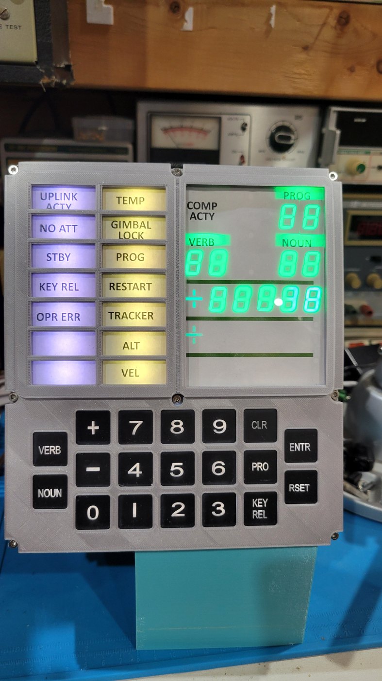
The lamps. Eighteen NeoPixel RGB LEDs are chained on a single data line from pin 6. In the code each lamp is simply a number from 0 to 17, and the firmware sets its colour with a one-line helper, lampit(r, g, b, lamp). Reading the code against my photographs gives the map: lamps 4 to 10 are the right-hand column from TEMP down to VEL, lamps 11 to 17 are the left-hand column from the bottom up to UPLINK ACTY (so NO ATT is lamp 16 and PROG is lamp 6), lamp 3 is COMP ACTY, and lamps 0 to 2 are the green PROG, VERB and NOUN legend blocks over the digits. The colours are chosen in software, too: the firmware lights the left column with equal red, green and blue (100, 100, 100), which comes out a cool white with a slight blue cast on the NeoPixels, and the right column with red and green only (100, 100, 0), which comes out yellow. That is the split the original panel used, white status lamps on the left and amber caution lamps on the right, and it is visible in Figure 1.
The keys and sensors. The nineteen keys are read through resistor ladders on three analogue inputs, one per keypad row: each key pulls its row’s voltage to a different level, and the firmware sorts the reading into a key by thresholds. The MPU-6050 gyro and accelerometer and the real-time clock share the I²C bus. The GPS receiver reaches the Nano’s serial port only through a reed relay on pin 7, so it stays off the line while the Nano is being reprogrammed over USB. The DFPlayer Mini MP3 module plays the audio clips from the SD card through a one-inch speaker, and it is driven by a single pin in a way that turns out to matter a great deal in Volume 21.
19.5 Power
The power switch is a round black rocker set into the side of the grey Mid Ring, between two moulded ribs (Figure 5). The Instructable’s enclosure step mounts “the Speaker and then the On/Off switch to the 3D Printed Mid Section,” and on my unit the switch sits on the left side as the panel faces the user. The kit’s power supply is a holder for six AA cells, nine volts in all, under the Battery Box Lid in the black rear, feeding a buck converter that brings it down to the five volts the Nano, the displays and the NeoPixels need. The Nano can also be powered over its USB socket, which is how it is reprogrammed.
19.6 The Plates
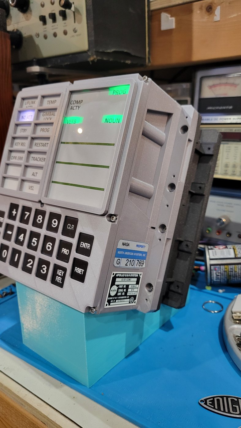
On the right side of my unit, below the display, are two plates in the style of 1960s government hardware (Figure 6). The upper one is a property tag: “NASA PROPERTY,” a blue band reading “NORTH AMERICAN AVIATION, INC.,” and the number “G 210 769.” North American Aviation built the Apollo Command Module, and its property tags were stuck on equipment throughout the program. The lower plate is a black-and-silver nameplate headed “APOLLO G&N SYSTEM,” with an “AGC DSKY ASSEMBLY” line, a NASA meatball, part, serial and contract numbers, and the legends “Designed by MIT Instrumentation Lab” and “Mfd by Raytheon Co.” That is the right attribution for the original: the MIT Instrumentation Laboratory designed the AGC and DSKY, and Raytheon built them (Volumes 3 and 15).
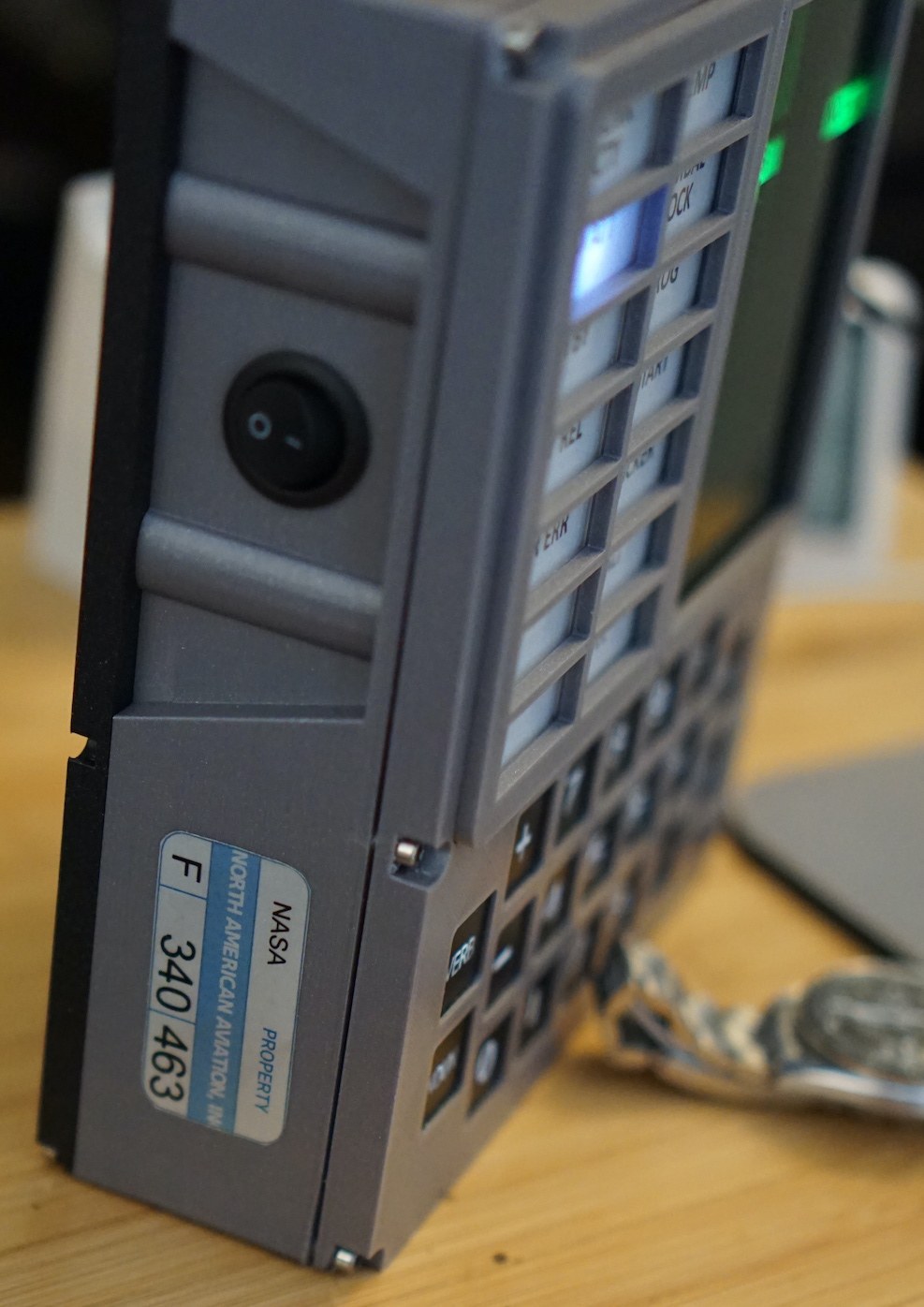
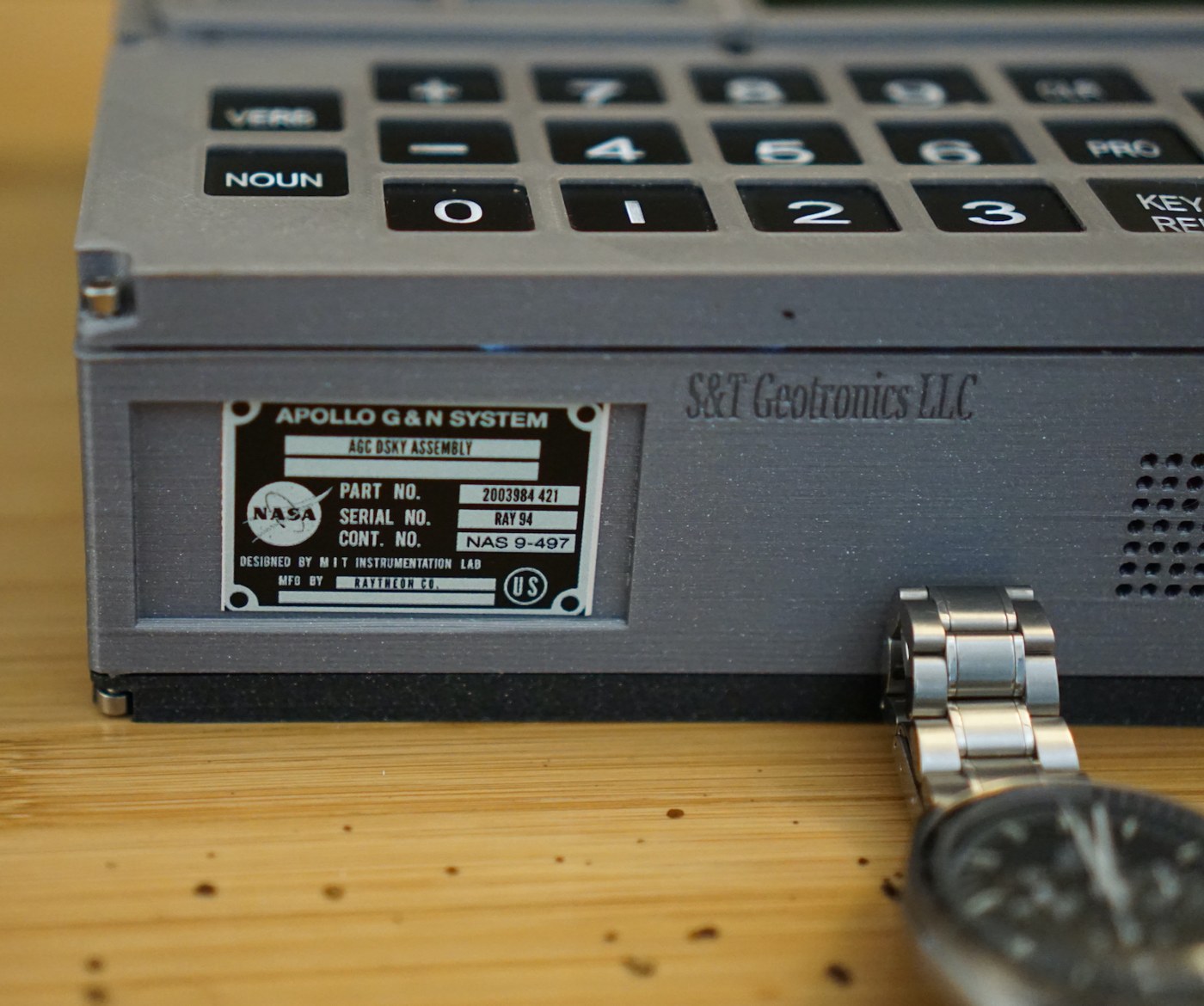
Both are almost certainly the stickers S&T supplies with the kit. Ken Stauffer’s review of his Open DSKY Slim kit says it came with “two stickers that you affix to the case which look like official NASA tracking signage,” and his photographs (Figures 7 and 8) show the same two designs: the same NASA / North American Aviation property tag (his reads “F 340 463,” so the numbers vary from kit to kit) and the same Apollo G&N System nameplate, set into a recessed panel beside an embossed “S&T Geotronics LLC.” The layout and wording of the nameplate on my unit match his line for line.
19.7 First Light: The Lamp Test
On the original DSKY, Verb 35 was the lamp test: it lit every warning lamp and drove every segment of every digit to an 8, so the crew could see at a glance that nothing had burned out before trusting the panel with their lives (Volume 9). Walker’s firmware keeps V35 as the lamp test, and it also runs nearly the same sequence by itself every time the unit is switched on.
The two routines are short enough to describe exactly. At power-on, setup() initializes the four MAX7219s at full brightness, wakes the MPU-6050, reads the clock, and calls startUp(). That routine flashes the RESTART lamp four times, lights the PROG, VERB and NOUN legend blocks green one after another, and then steps through the lamps one at a time, fifty milliseconds apart, white on the left and yellow on the right. Then it sweeps the digits: for each of the four driver chips in turn, it sets each of six digit positions to 8, twenty-five milliseconds apart. That runs the 88s of PROG, VERB and NOUN first, then the first register, then the second and third. It holds the full panel for a second and clears it.
The V35 lamp test, in a routine the code calls mode4(), does the same lamp and digit sweep, adds the green COMP ACTY lamp, and then flashes the VERB and NOUN digits, the KEY REL lamp and the OPR ERR lamp together four times, half a second on and half a second off, before restoring the display. The flashing is a nice touch: on the original, a flashing VERB and NOUN meant the computer was waiting for the crew, and the lamp test exercised that too.
Figure 1 is that sequence caught partway. Every warning lamp is lit, white on the left and yellow on the right; PROG, VERB and NOUN read 88; the first register reads +88888; and the second and third registers have not yet filled. COMP ACTY is dark in the photograph, which fits the power-on sweep (which does not light it) rather than V35 (which does), but the camera could also have caught COMP ACTY between updates, so the photograph alone does not settle it.
19.8 The Idle Panel
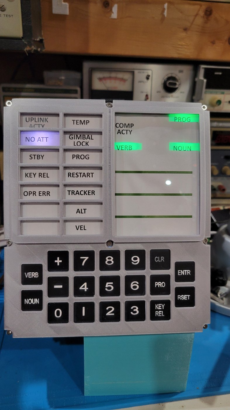
When the start-up sweep finishes, the panel settles into the state shown in Figure 2: every register blank, the PROG, VERB and NOUN legend blocks lit green, and one warning lamp on, NO ATT.
That lamp is set deliberately. The last lines of setup() turn COMP ACTY off and set lamp 16, NO ATT, to white. On the real spacecraft, NO ATT meant “no attitude”: the inertial measurement unit was not available as an attitude reference, for example when it was caged or not yet aligned. On a replica sitting on a bench, with no inertial platform at all, it is the most honest lamp on the panel. The firmware puts it out again when one of the IMU displays is called up (the routines that read the MPU-6050’s gyro or accelerometer each begin by extinguishing lamp 16), so the lamp tracks, loosely, whether the replica’s own small IMU is in use.
From this state the panel waits for a verb. The keying is the same as on the original: VERB, two digits, NOUN, two digits, ENTR. The commands themselves, and the manual I use to look them up, are Volume 20.
19.9 On My Bench
The photographs in this volume were taken where the unit lives: on the blue mat of my electronics bench, under a shelf of test gear. Behind it in the pictures are a Micronta variable DC power supply, an older bench supply with a moving-coil meter, and a Stanford Research Systems instrument; a pair of Enigma badges lies on the mat beside it, a reminder of the Open Enigma I built from the same workshop’s kit. The DSKY is the newest thing on the shelf by fifty years in design and the oldest by fifty years in what it imitates.
19.10 What the Build Adds Up To
Laid out part by part, the Open DSKY is an Arduino Nano, four display drivers, eighteen RGB LEDs, a keypad on three analogue pins, three sensor modules, an MP3 player and a printed case. Put together in the case, with the stickers on its side and the lamp test running, it is something more particular: a working copy of the interface that the Apollo crews used, behaving according to its own grammar. Walker’s firmware gives it the vocabulary, and the printed Command Reference sets that vocabulary out the way a crew’s checklist did.
Next — Volume 20: The Command Reference. The printed, ring-bound manual I run my Open DSKY from: Bill Walker’s Apollo Open DSKY Command Reference, every verb, noun and program it documents, how each maps to the firmware, and how it compares with the checklists the crews flew with.
Comments (0)