M-209 · Volume 9
M-209 — Volume 9 — Building an M-209 — Assembly, Setting the Key and Testing
Putting the replica together in an order that tests each assembly before the next one hides it; zeroizing it and setting the 1944 manual's own training key list; the 26-letter check; acceptance tests against the simulator; and how a periodic or a scattered garble points to the faulty pin or lug
9.1 About This Volume
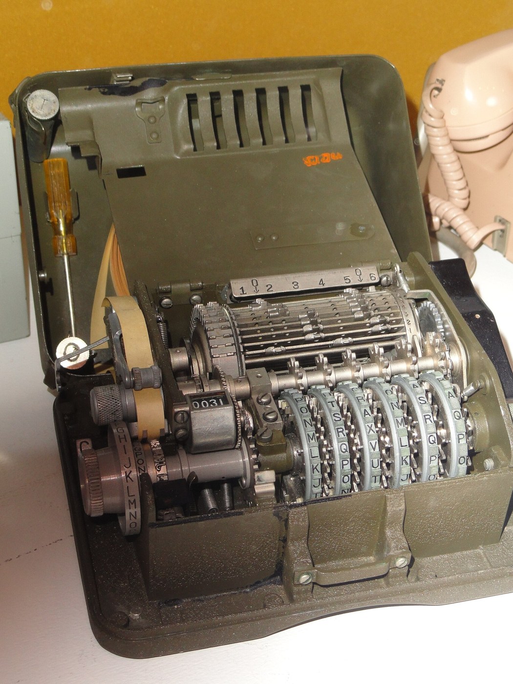
Volume 8 specified a mechanical M-209 replica: printed key wheels gripping 131 steel pins, a drum of 27 printed bars with sliding lug clips, a typewheel turned by the ends of kicked bars, and a stepping cam that moves six ratchets. This volume puts it together and proves that it works.
The proof is the same one the Army used. A correctly set M-209 enciphering 26 A’s from AAAAAA prints a 26-letter string fixed by its pins and lugs, and the key list prints that string beside the settings: if the tape and the list agree, the machine is set right (TM 11-380, par. 8e). The 1944 manual prints a training key list with its check, TNJUW AUQTK CZKNU TOTBC WARMI O, and the unit’s simulator reproduces it. A replica that prints the same 26 letters from the same settings is doing what an M-209 does; one that does not has a fault, and the pattern of wrong letters says where.
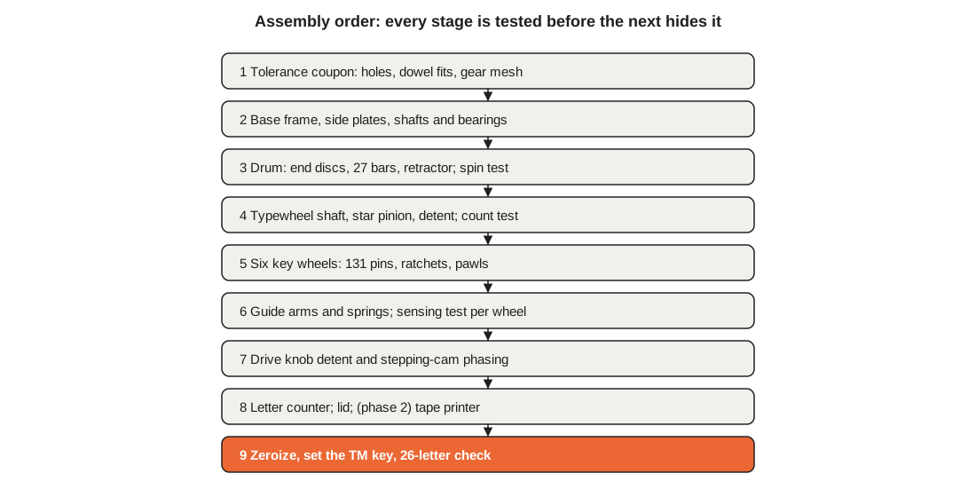
The volume runs in build order: the tolerance coupon, then the frame, drum, typewheel, wheels, arms and drive, each with a test that has to pass before the next assembly goes on top of it. Then the key is set, the checks are run, and the faults that the checks reveal are diagnosed with the manual’s own method.
Nothing here has been built yet; the procedures are designs. The places for the account of the real build are marked.
9.2 Stage 1: The Tolerance Coupon
Print the coupon of Volume 8 before anything else: a 2.0 mm pin hole, a 1.6 mm hole in TPU, an 8.1 mm bushing bore, a notched bar section with one lug clip, and a pair of module 2 gear teeth. It takes under an hour and decides four numbers for every later part.
- Pin fit. Ream the 2.0 mm hole with a 2.0 mm drill turned by hand in a pin vice. A dowel should slide through with no play that can be felt and no force. If it binds, enlarge the drawn hole by 0.05 mm and reprint; if it rattles, reduce it.
- Pin grip. Push a dowel through the TPU hole. It should need a firm push with a fingertip and stay put when the coupon is shaken pin-down. Too loose: draw the hole at 1.5 mm. Too tight to set comfortably 131 times: 1.7 mm.
- Lug clip. Slide the clip along the bar section. It should click into each notch and need a definite push to leave it. A clip that will not stay in a notch will let the arms drag it; one that needs a tool will make setting 54 lugs miserable.
- Bushing and teeth. An 8 mm rod should turn in the bore without wobble; the two gear teeth should mesh with a visible but small backlash.
Record the final hole sizes in the CAD file, and keep the coupon: it is the reference for every reprint.
9.3 Stage 2: Frame, Shafts and Bearings
Set M3 heat-set inserts into the base tray and side plates (220 °C, square to the surface). Press the two 688ZZ drum bearings and the two 686ZZ typewheel bearings into their seats in the side plates, and fit the plates to the base. Slide the 8 mm drum shaft and the 6 mm typewheel shaft through with nothing on them.
Test. Each shaft must spin freely by a flick of the finger and coast. Any rubbing now will be impossible to find once 27 bars and a gear are on the shaft. Check that the two shafts are parallel by measuring their spacing at both side plates; the drum’s bar ends and the typewheel gear will not mesh evenly along their width otherwise.
9.4 Stage 3: The Drum
Fit the two end discs to the drum shaft and slide the 27 bars into their slots. Number the bars 1 to 27 on the right end disc, as on the original (TM 11-380, par. 21a), and mark the left end disc with the notch positions 1 0 2 3 4 5 0 6 on a number plate behind the drum. Fit the friction O-rings. Fit no lug clips yet.
Tests.
- Slide. Push each bar 4 mm left and back by hand. It must move freely and stay where it is put.
- Spin. Turn the drum by the shaft. No bar may touch anything.
- Retractor. Push a few bars left and turn the drum once. The retractor ramp must return every one of them to the right before it reaches the arm side. A bar left out is a count error waiting to happen.
9.5 Stage 4: The Typewheel and the Count
Fit the typewheel shaft parts: setting knob, indicating disk, reproducing disk, detent wheel, typewheel gear. Align the disks so that A on the indicating disk shows Z on the reproducing disk, with the detent in a notch.
This is the stage that decides whether the machine can count, so it gets the most thorough test. Without key wheels or guide arms fitted, a bar can be kicked by hand.
Count test. Set the indicating disk to A. Push n bars to the left by hand, turn the drum one full turn with the drive knob, and read the reproducing disk. It must show the letter n places on from Z, wrapping round to A: A for 1 bar, B for 2, J for 10, Y for 25, Z for 26 (a full turn of the typewheel), A again for 27. Repeat with the kicked bars in different places round the drum — all together, spread out, the first and last. Every combination must give exactly n.
A count that is one short means a bar end missed the gear; one too many means a bar end struck two teeth or the detent jumped a notch. Both point to the bar ends not lying on the 81 mm pitch circle or to too much backlash. Fix it here: every cipher letter depends on this mesh.
9.6 Stage 5: The Key Wheels
Assemble each wheel sandwich — disc A, TPU ring, disc B — with its three M3 screws, then push in its pins: 26, 25, 23, 21, 19 and 17. Set every pin to the left. Slide the six wheels onto the 8 mm key-wheel shaft in order, wheel 1 at the left, with the detent fingers and pawls in place, and fit the E-clips.
Tests.
- Letters. Check each wheel’s lettering against the table in Volume 3: wheel 2 has no W, wheel 3 no W and stops at X, wheel 6 stops at Q.
- Offset. Turn each wheel until A is at the bench mark. The pin now at the sensing position, under the wheel at the guide-arm side, must be P on wheel 1, O on wheel 2, N, M, L and K on wheels 3–6 (TM 11-380, par. 15b). The arrows moulded on disc B (Volume 8) show it; check it by pushing that one pin right and watching for it at the sensing position.
- Detent. Each wheel must click into each letter position, square to the bench mark.
9.7 Stage 6: The Guide Arms
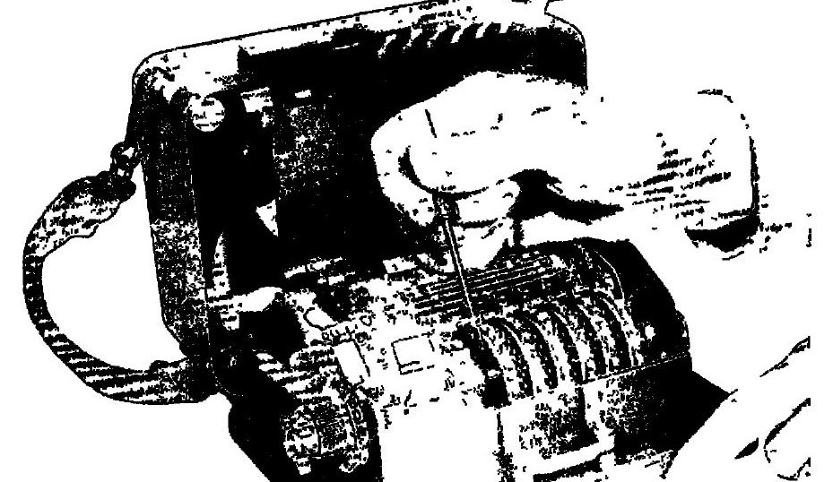
Fit the six guide arms on their 4 mm rod with the comb between them, and hook on their springs.
Sensing test, one wheel at a time. With all pins on all wheels set left, every arm must stay back, clear of the drum. Then, for each wheel in turn, push the pin at the sensing position to the right: that wheel’s arm, and only that one, must swing forward into its lug lane. Step the wheel by hand: as the next (left) pin comes round, the arm must be pushed back smoothly, with no catch.
Lane test. Fit one lug clip on bar 1 in position 3, push wheel 3’s sensing pin right, and turn the drum slowly. The arm’s ramp must meet the clip squarely and push bar 1 fully left; the clip must stay in its notch. Repeat for each of the six lanes, and check that a clip in either 0 position passes every arm untouched.
9.8 Stage 7: Drive, Stepping and the Counter
Fit the drive knob with its home detent, the stepping cam, the pawl bar and pawls, and the letter counter.
Phasing test. This is the subtle one. The wheels must step only while the empty third of the drum is passing the arms (Volume 8). Mark the drum where the last bar passes the arms and where the first bar arrives. Turn the knob slowly from home: the pawls must start to move only after the last bar has passed, and the wheels must be fully stepped and settled in their detents before the first bar comes round. A machine that steps early still works and still prints letters — but some of them are computed from the next letter’s pins. Only the 26-letter check will show it, so check the phasing by eye now.
Counter test. Twenty-six turns of the knob must advance every wheel by 26 positions — so wheel 1 is back where it started, wheel 6 is 9 letters on — and the counter by exactly 26.
9.9 Setting a Key
The 1944 manual’s procedure (par. 8) is followed exactly, because the point is to set the replica the way a signal clerk set an M-209.
Zeroize. Push every pin on every wheel to the left (ineffective). Slide every lug clip to a 0 position: left clips to the left 0, right clips to the right 0. The manual requires this at the end of every period of use, so that a captured machine reveals nothing (par. 12), and it is the starting point for setting any new key.
Set the pins. Work through Table I of the key list wheel by wheel. Every letter printed in a wheel’s column means “push this pin to the right”; a dash means “leave it at the left”. For the training key list in the 1944 manual (transcribed in Volume 4, and built into the simulator as TM_KEY) the effective pins are:
Table 1 — Set the pins. Work through Table I of the key list wheel by wheel. Every letter printed in a wheel's column means "push this pin to the right"; a dash means "leave it at the left". For the training key list in the 1944 manual (transcribed in Volume 4, and built into the simulator as TMKEY) the effective pins are
| Wheel | Effective pins |
|---|---|
| 1 | A B D H I K M N S T V W |
| 2 | A D E G J K L O R S U X |
| 3 | A B G H J L M N R S T U X |
| 4 | C E F H I M N P S T U |
| 5 | B D E F H I M N P S |
| 6 | A B D H K N O Q |
That is 12, 12, 13, 11, 10 and 8 pins: 66 to push right. Push each one fully home.
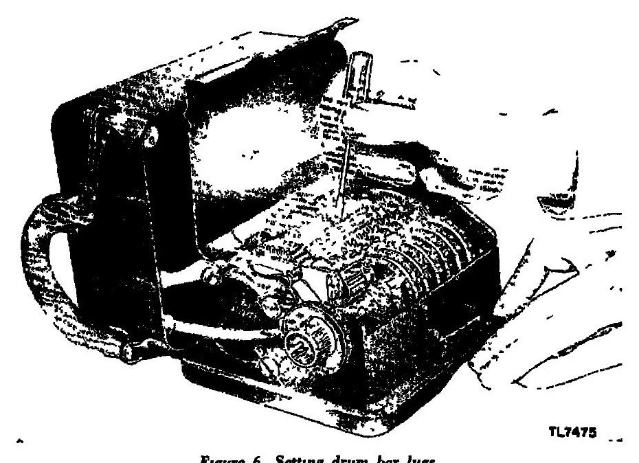
Set the lugs. Work down Table II. Each entry gives the positions of the two lugs on one bar: “3-6” means one clip at 3 and one at 6; “0-4” means one at a 0 and one at 4. For the training key list:
Table 2 — Set the lugs. Work down Table II. Each entry gives the positions of the two lugs on one bar: "3-6" means one clip at 3 and one at 6; "0-4" means one at a 0 and one at 4. For the training key list
| Bars | Lugs |
|---|---|
| 1 | 3-6 |
| 2 | 0-6 |
| 3 | 1-6 |
| 4 | 1-5 |
| 5 | 4-5 |
| 6–9 | 0-4 |
| 10–19 | 2-0 |
| 20–21 | 2-5 |
| 22–27 | 0-5 |
Following the manual’s advice, keep each bar’s left clip in 1, 2, 3 or the left 0 and its right clip in 4, 5, 6 or the right 0 (par. 8d).
Count test with the real lugs. Before the full check, one quick test separates lug errors from pin errors. Temporarily push all the pins of one wheel right and all others left, so that only that wheel’s arm is ever active, and encipher a few A’s. With the training lugs set correctly, the simulator says each wheel alone must give a constant letter equal to the number of bars it engages:
Table 3 — Count test with the real lugs. Before the full check, one quick test separates lug errors from pin errors. Temporarily push all the pins of one wheel right and all others left, so that only that wheel's arm is ever active, and encipher a few A's. With the training lugs set correctly, the simulator says each wheel alone must give a constant letter equal to the number of bars it engages
| Wheel active alone | Bars engaged | A enciphers to |
|---|---|---|
| 1 | 2 | B |
| 2 | 12 | L |
| 3 | 1 | A |
| 4 | 5 | E |
| 5 | 10 | J |
| 6 | 3 | C |
| none | 0 | Z |
| all six | 27 | A |
A wrong letter here means a wrong lug on that wheel’s lane. Then reset the pins from Table I.
9.10 The 26-Letter Check
With pins and lugs set: zeroize the letter counter, turn the knob to C, turn all six wheels to A, set the indicating disk to A, and turn the drive knob 26 times, moving the indicating disk off A and back between turns as the original’s drum lock requires (par. 8e). Read the 26 results from the reproducing disk, or from the tape in phase 2. They must be:
TNJUW AUQTK CZKNU TOTBC WARMI O
“If the tape and the 26-letter check are identical, the pin and lug settings are correct; if they differ by one or more letters, there is an error in the initial settings of the converter which must be corrected before proceeding” (par. 8e).
9.11 Acceptance Tests
The 26-letter check proves the setting. The full acceptance series proves the machine, by comparing it with the simulator on several keys and a real message. Each result is what m209_sim.py prints for the same settings.
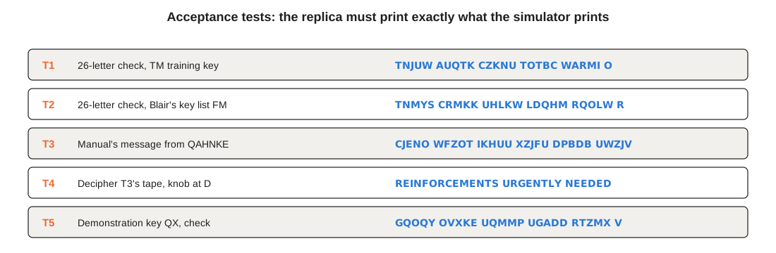
- T1 — training key, 26-letter check. As above: TNJUW AUQTK CZKNU TOTBC WARMI O.
- T2 — a second, independent key. Mark Blair’s key list FM, published with its check in his “Practical Use of the M-209 Cipher Machine” (nf6x.net, chapter 3): lugs 1-0, 2-0 ×8, 0-3 ×7, 0-4 ×5, 0-5 ×2, 1-5, 1-6, 3-4, 4-5; pins BCEJOPSTUVXY / ACDHJLMNOQRUYZ / AEHJLOQRUV / DFGILMNPQS / CEHIJLNPS / ACDFHIMN. Check: TNMYS CRMKK UHLKW LDQHM RQOLW R. Passing on a second key list catches a fault that the first happens to hide.
- T3 — a message. Training key, wheels set to QAHNKE, counter zeroized, knob at C: encipher REINFORCEMENTS URGENTLY NEEDED with Z for each space. Result: CJENO WFZOT IKHUU XZJFU DPBDB UWZJV (Volume 7 traces it letter by letter).
- T4 — deciphering. Reset the wheels to QAHNKE, counter to zero, knob to D, and dial the 30 cipher letters. Result: REINFORCEMENTS URGENTLY NEEDED, with blanks for the two Z’s in phase 2, or Z’s read from the disk in phase 1.
- T5 — the demonstration key list. The unit’s demonstration key list “QX” (
m209_sim.py --demo-key) has the six overlaps and full 1–27 coverage the manual requires. Lugs 1-2, 2-5, 3-0 ×10, 3-5, 3-6, 0-4, 0-5 ×7, 0-6 ×3, 4-5, 4-6; pins ABCHIJNOQSWX / BDFGJKMNPRUV / ABDFHKLMOPRTU / DIJKMNOPT / ACEGHJOPQRS / CEHJKNOP. Check: GQOQY OVXKE UQMMP UGADD RTZMX V. This is the key Volume 10 sends and breaks traffic on.
A replica that passes all five is interchangeable with a wartime M-209: a message it enciphers can be read on an original, and the reverse.
9.12 When the Check Fails
The 1944 manual’s section on garbles (par. 15) is a fault-finding guide for exactly this situation, and it works as well on a replica as it did in the field. The trick is to look at where the wrong letters are.
9.12.1 A periodic error: one pin
“One incorrectly placed key wheel pin will result in garbled text. This type of garble is recognized by a single-letter error appearing periodically in the text, i.e., by errors which are an equal distance apart” (par. 15b). The distance names the wheel: 17 letters for wheel 6, 19 for wheel 5, 21, 23, 25 and 26 for wheels 4 to 1.
The simulator shows it. If pin K on wheel 6 of the training key were left at the left instead of pushed right, the 26-letter check would come out RNJUW AUQTK CZKNU TORBC WARMI O — wrong at letters 1 and 18, seventeen apart. Wheel 6. To find the pin, the manual says: turn the letter counter back to the last good letter, so the wheels stand where they stood for the bad one, then count over the top of the wheel from the letter at the bench mark — 16 on wheel 1, 15, 14, 13, 12 and 11 on wheel 6, counting the bench-mark letter as one (par. 15b). For letter 1 the wheels stood at AAAAAA; counting 11 on wheel 6 from A gives K. That is the pin.
The manual’s own example uses a deciphered sentence, NOW IS THE TIME FOR ALL GOOD MEN, garbled by a wheel-6 pin. The simulator reproduces the effect on the training key from QAHNKE with pin E of wheel 6 set wrongly on the receiving machine: the text comes out NOW IS VHE TIME FOR ALL IOOD MEN, wrong at letters 8 and 25 — again 17 apart. With the counter turned back to 7, the last good letter, the wheels stand where they stood for letter 8; wheel 6 shows L (E moved on seven places), and counting 11 from L over the top of a 17-letter wheel (L, M, N, O, P, Q, A, B, C, D, E) arrives at E.
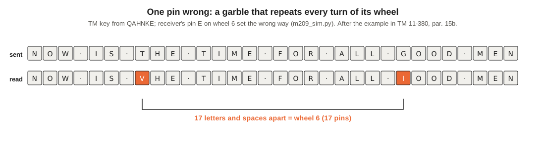
On the replica, a periodic error has three possible causes: a pin set wrongly from the table; a pin set correctly but not pushed fully home, so the follower nose half-reads it; or a follower nose that does not drop into the gap of a flush pin because its spring is weak. The first is fixed by resetting the pin, the second by pushing it home, the third by a stronger spring or by easing the nose.
9.12.2 A scattered error: one lug
“Garbles caused by an incorrectly set drum bar lug are recognized by a nonperiodic appearance of errors” (par. 15c). A lug affects every letter on which its wheel’s arm is active, and those letters come at irregular intervals set by all the pins of that wheel.
The simulator again: with bar 1 set 3-5 instead of 3-6, the training key’s 26-letter check comes out wrong at letters 2, 3, 4, 9, 13, 14, 15, 16, 25 and 26 — ten wrong letters with no common spacing. With bar 10 set 0-0 instead of 2-0 (a clip left in a 0 position), thirteen letters are wrong. A scattered error means: re-check Table II bar by bar, and then use the single-wheel count test above, which isolates the lane.
On the replica a scattered error has two mechanical causes as well: a clip that the arm pushed out of its notch, or a bar that the retractor failed to return. Both show up as errors that come and go between runs, which a setting error never does.
9.12.3 Errors that do not fit either pattern
Table 4 — Errors that do not fit either pattern
| Symptom | Probable cause | Remedy |
|---|---|---|
| Every letter wrong, check starts with Z | No arm ever active | Springs unhooked; follower noses jammed |
| Some letters wrong by exactly one place | Bar end missed or double-struck the typewheel gear | Repeat the stage 4 count test |
| Correct for a while, then wrong from one letter on | A wheel failed to step, or stepped twice | Pawl spring; detent too stiff |
| Matches simulator only when turned slowly | Stepping phased early | Re-time the stepping cam (stage 7) |
| Check correct, but messages from an original M-209 fail | Wheel lettering or offset wrong on one wheel | Re-check stage 5 tests 1 and 2 |
The last row matters most for a replica. A machine whose wheels are lettered or offset wrongly can still pass a 26-letter check if it was designed from a wrong simulator — the check would match the wrong simulator. That is why this series’ simulator is tested against a check printed in the manual and against letter checks from a real machine, not against itself.
9.13 Looking After It
Two habits from the 1944 manual carry over directly. Zeroize at the end of every session — pins left, lugs to 0 — so that no key stays set in an unattended machine (par. 12). And never force the drive knob: the manual’s caution that a lug left between holes “will jam the machine” (par. 8d) applies equally to a clip left between notches, and a printed bar bends more easily than a steel one.
Next — Volume 10: Using the M-209 — A Field Message, Sent and Broken. A day’s traffic on key list QX sent in wartime procedure, two messages carelessly sent with the same indicator, and the German Army’s method — a probable word dragged through the depth, the counts written in columns, the pins and lugs fitted, the wheels fixed from the indicator — run on the simulator in seconds to read every message of the day.
Comments (0)