M-209 · Volume 3
M-209 — Volume 3 — How the M-209 Works — Pins, Lugs, the Drum and the Print Wheel
Six key wheels and their 131 pins, the guide arms that read them, a drum of 27 bars that behaves like a gear with a variable number of teeth, a print wheel lettered backwards, and one letter followed all the way through the machine
3.1 About This Volume
Volume 1 described the M-209 in five steps. This volume takes the lid off and follows the parts in the order a letter meets them: the indicating disk on which the operator dials it, the six key wheels and their pins, the guide arms that sense those pins, the drum of 27 bars that counts how many arms are active, the print wheel that turns by that count and prints the result, and the train of cams that steps the wheels, feeds the tape, spaces the groups and keeps the letter counter. It ends with one letter traced through the machine on the War Department’s own training key.
The primary source throughout is the 1944 edition of the Army’s manual, TM 11-380, Converter M-209, M-209-A, M-209-B (Cipher), dated 17 March 1944 (NSA Friedman Collection, REF ID A67854), whose Section III, “Functioning of Parts”, describes each assembly with an exploded drawing. Paragraph numbers below refer to that edition. Every numerical example comes from the unit’s simulator, 03-outputs/tools/m209_sim.py, which reproduces the 26-letter check printed in the same manual (Volume 4 describes the check; Volume 9 uses it to test the replica).
3.2 The Machine from the Outside
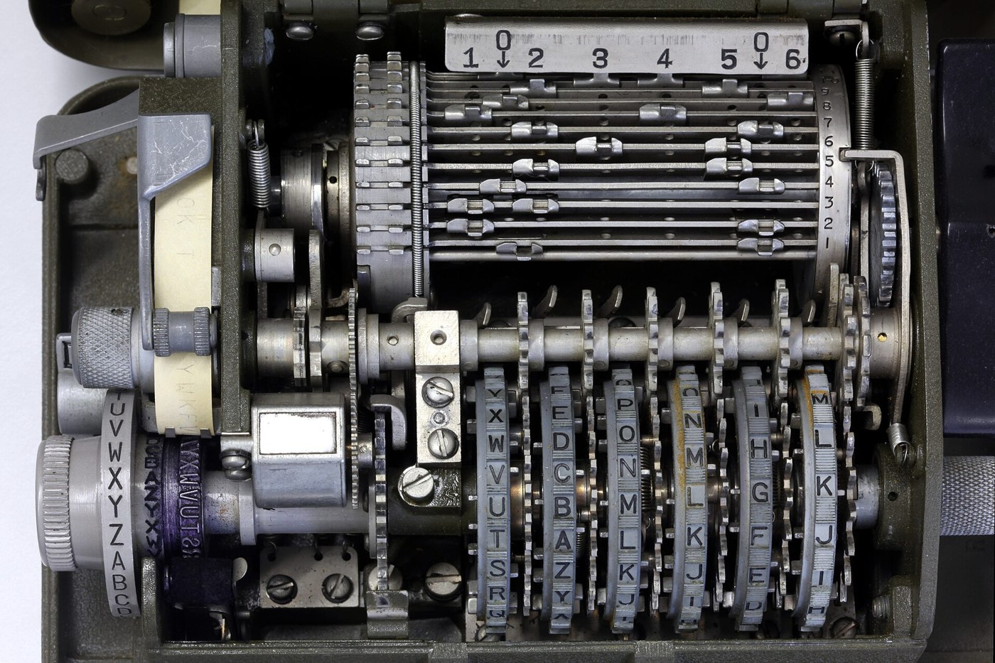
Closed, the M-209 is a dull olive-drab box of 178 × 140 × 83 mm weighing about 2.7 kg (Crypto Museum). With the outer cover open, the operator sees an inner lid with a row of six windows along its front edge, through which the rims of the six key wheels show their letters; a white bench mark beside the windows shows which letter of each wheel counts as “set”. At the left end are two concentric disks on one shaft: the large indicating disk, lettered A to Z in normal order and turned with a knurled setting knob, and just inside it the smaller reproducing disk, lettered in reverse order, of which four letters show through a reading window. On the right is the black drive knob. A letter counter reading 0000 to 9999 sits in a window at the front left, and a small encipher–decipher knob marked C and D sits below the paper-feed knob. A roll of narrow gummed paper tape feeds out past the left end of the inner lid (TM 11-380, par. 5).
To encipher, the operator turns the indicating disk until the plain letter lines up with the indicating index, then turns the drive knob one full turn until it locks. The machine prints the cipher letter on the tape. The drive knob will not turn again until the indicating disk has been moved; a double letter therefore needs the disk turned away and back (par. 10c(5)). Deciphering is the same motion with the C–D knob at D. Nothing else changes, because the cipher is its own inverse.
Everything that makes the substitution change from letter to letter happens under the inner lid.
3.3 The Key Wheels
There are six key wheels, mounted side by side on one shaft. Each has a different number of letters engraved on its rim (par. 5a):
Table 1 — There are six key wheels, mounted side by side on one shaft. Each has a different number of letters engraved on its rim (par. 5a)
| Wheel | Letters | Positions |
|---|---|---|
| 1 | A–Z | 26 |
| 2 | A–Z, omitting W | 25 |
| 3 | A–X, omitting W | 23 |
| 4 | A–U | 21 |
| 5 | A–S | 19 |
| 6 | A–Q | 17 |
Just below each letter a small pin projects from one side of the wheel or the other. It slides sideways in a slot through the wheel: pushed to the right it is effective, pushed to the left it is ineffective. The six wheels carry 26 + 25 + 23 + 21 + 19 + 17 = 131 pins, and the pattern of right and left across all of them is half of the internal key. The pins are set by hand, with the tip of a pencil or the special screwdriver kept in the lid, from Table I of the key list (par. 8b); “each pin must be moved all the way to the left or right,” the manual warns, or the text will garble.
3.3.1 Stepping
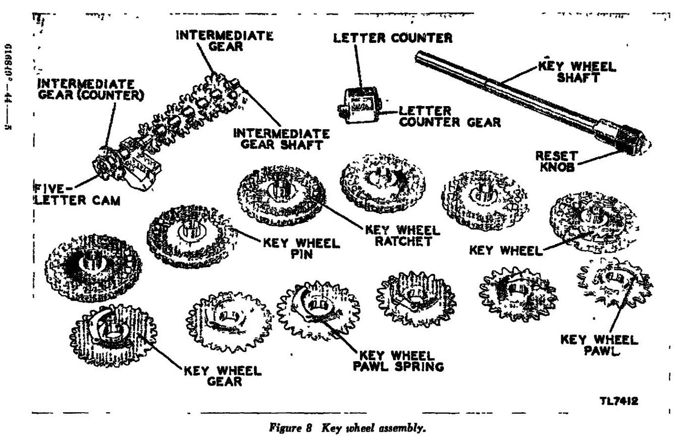
After every letter all six wheels advance by one position. The motion comes from the drum shaft: a feed cam on the right drum disk moves a set of intermediate gears behind the wheels one notch per turn of the drive knob, and each intermediate gear drives a gear on its key wheel. The manual explains the one awkward detail: each wheel has one gear tooth per pin, so a 26-pin wheel and a 17-pin wheel have gears of different pitch, and the intermediate gears “vary in circumference and number of teeth” so that every wheel moves exactly one pin per letter (par. 19b). A ratchet and pawl on each wheel let the operator turn any wheel forward by hand to set it, but only in one direction; a reset knob on the end of the shaft, with the reset button pressed, turns all six together in either direction and zeroes the letter counter (pars. 5a, 19c).
Because the wheels always step together, the six letters in the windows march forward as a block — AAAAAA, BBBBBB, CCCCCC — until the shorter wheels run out of letters and wrap round. Wheel 6 comes back to A after 17 letters, wheel 1 only after 26. Volume 7 shows what that does to the period of the machine.
3.3.2 The pin that counts is not the pin in the window
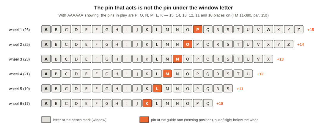
The letters in the windows are only a reference. The pin that actually acts on each letter is the one at the sensing position, out of sight under the wheels, where it meets a guide arm — and that is a fixed number of places round the wheel from the letter at the bench mark. The 1944 manual gives the distances in its section on garbles, where an operator hunting a mis-set pin is told to count “over the top of the key wheel which contains the error, beginning with the letter which is on line with the bench mark”: 16 letters on wheel 1, 15 on wheel 2, 14, 13, 12 and 11 on wheels 3 to 6, counting the bench-mark letter as the first. “If A were aligned on the key wheels, the pin in operation for the next letter would be the one associated with the letter P for wheel number 1, O for wheel number 2, N for wheel number 3, and so forth” (par. 15b).
So with AAAAAA showing, the pins in play are P, O, N, M, L and K: offsets of 15, 14, 13, 12, 11 and 10 places. Every simulator has to get this right, and it is the commonest source of error in home-made ones. It is built into m209_sim.py as the letter in play when A is showing, exactly as the manual states it.
3.4 The Guide Arms
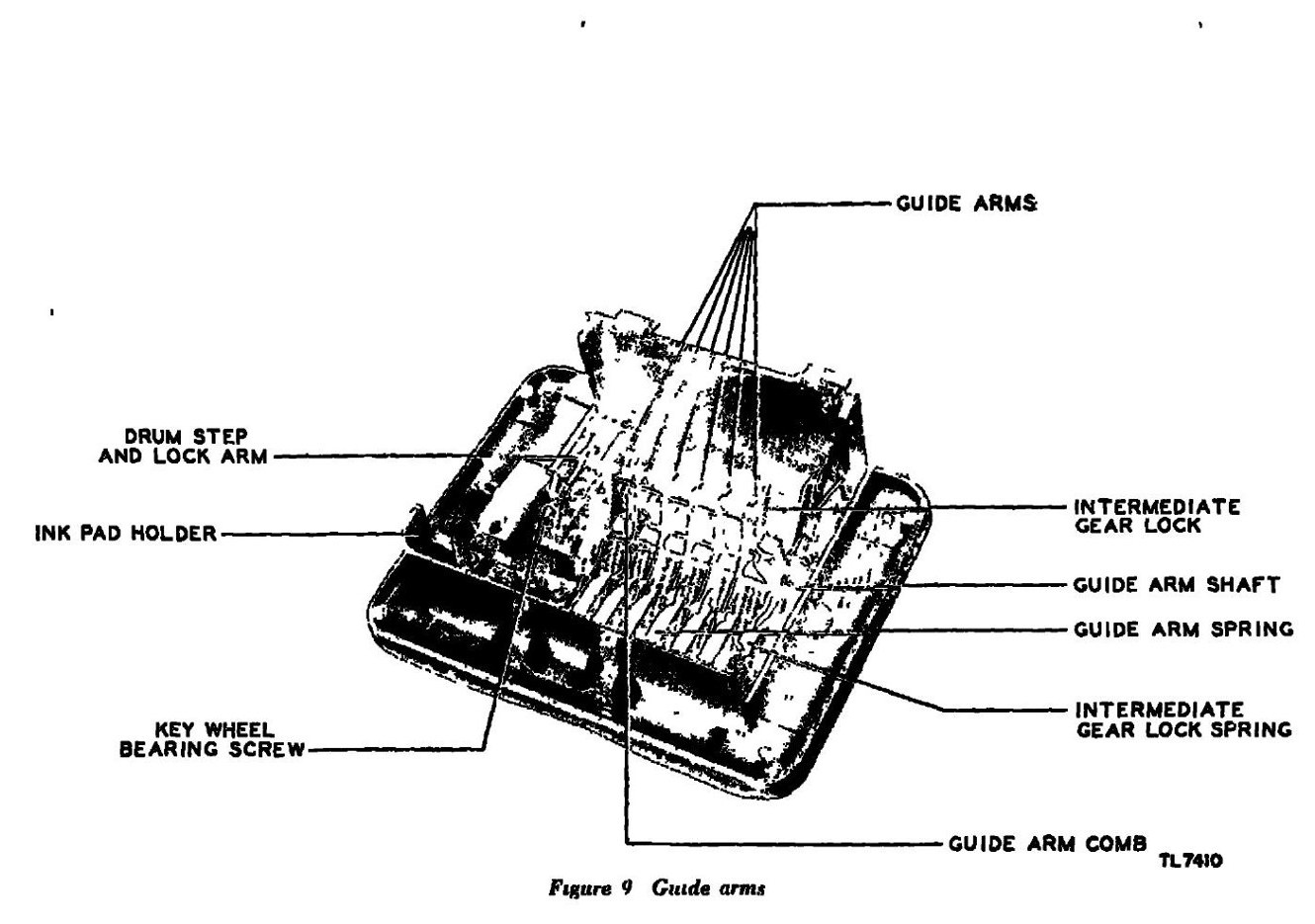
Between the key wheels and the drum lie six guide arms, one for each wheel, pivoting on a common shaft (par. 20). Each arm is pushed toward the drum by its own spring and held back by the pin at the sensing position of its wheel. “When a key wheel pin in the effective position comes into play the associated guide arm is released allowing the guide arm spring to push the guide arm toward the rear of the machine. In this position, the guide arm will, when the drum is rotated, make contact with the drum bar lugs in line with it.” A pin in the ineffective position “holds the guide arm it controls in an inactive position”, and an inactive arm has no effect on that cycle.
The guide arms are therefore six one-bit switches, re-read at every letter. At any moment the state of the machine’s moving key is just six yes-or-no answers: is the pin now in play on wheel j effective or not? Everything else in the mechanism exists to turn those six bits into a single number.
3.5 The Drum
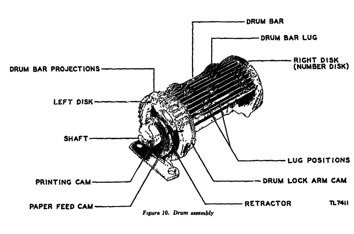
Behind the guide arms is the drum, sometimes called the lug cage: a shaft with two disks, between which run 27 drum bars, numbered on the right-hand disk and occupying about two-thirds of the drum’s circumference (pars. 5j, 21). The drum turns once, through a full revolution, for every turn of the drive knob.
3.5.1 Lugs
Each bar carries two movable lugs, and each lug can sit in any one of eight positions along the bar, marked on a number plate behind the drum in the order
1 0 2 3 4 5 0 6
The six numbered positions lie directly in front of the six guide arms; the two zero positions lie between them and meet no arm (par. 21b). A lug is moved by pushing it slightly toward the front of the machine to free it from its hole, sliding it along and letting it click into the new hole; one left between holes “will jam the machine” (par. 8d). The positions of the 54 lugs are the other half of the internal key, set from Table II of the key list in the shorthand “3-6”, “0-4” and so on, which gives the positions of the left and right lugs of each bar. The manual recommends keeping each bar’s left-hand lug in positions 1, 2, 3 or the left zero and its right-hand lug in 4, 5, 6 or the right zero (par. 8d), which avoids two lugs trying to occupy the same hole and makes the table quicker to set.
3.5.2 Kicking the bars
As the drum turns, every bar passes every guide arm in turn. If a bar carries a lug in the lane of an arm that is pushed forward, the arm pushes the lug, and with it the whole bar, sideways to the left: “The drum bar lugs are forced, one after the other, to the left. In the left position the drum bar lugs act as cogs of a wheel, meshing with the typewheel intermediate gear, which turns the typewheel. The typewheel is turned as many letters as there are bars projecting from the left of the drum” (par. 21c). A retractor pushes each bar back to its neutral position after it has done its work.
Three consequences follow, and they are the heart of the machine.
- A bar counts once or not at all. A bar is kicked if either of its lugs meets an active arm. If both lugs face active arms, it is still kicked only once. The count for a letter is therefore not a simple sum of the lugs facing active arms; it is the number of bars with at least one such lug.
- The count runs from 0 to 27. With no arm active, no bar moves; with every arm active and every bar carrying at least one effective lug, all 27 move.
- The drum is a gear with a variable number of teeth. The kicked bars are the teeth; the rest of the drum is toothless. Hagelin’s own phrase for it was that the drum “acts like a gearwheel with a variable number of teeth” (Hagelin, The Story of the Hagelin Cryptos, p. 25). One turn of the drive knob turns the typewheel by exactly as many letters as there are teeth.
Writing x₁ … x₆ for the six guide-arm bits (1 if the pin in play on that wheel is effective), the count for one letter is
k = number of bars b for which some lug of b sits in a lane j with xⱼ = 1.
That one sentence is the entire keying function of the machine. Volume 7 shows how a key list’s choice of lugs turns the 64 possible patterns of six bits into counts, and why the Army insisted that every count from 1 to 27 be reachable.
3.5.3 The drum lock
At the end of each revolution, a cam on the left drum disk pushes the drum lock arm into place, and a projection on the lock arm drops between two teeth of the typewheel gear. “The drum remains locked until the typewheel is turned” (par. 21c). This is the interlock that forces the operator to move the indicating disk between letters. It also holds the typewheel firmly on a letter while it prints, so that a half-letter cannot be printed between two type faces.
3.6 The Typewheel and the Reversed Alphabet
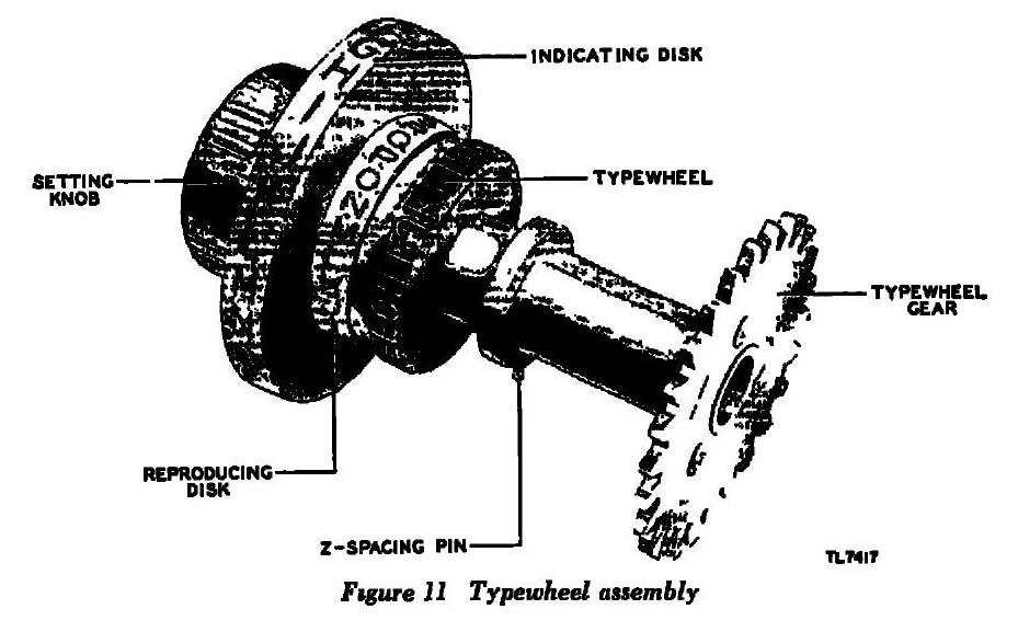
The setting knob, the indicating disk, the reproducing disk, the typewheel and the typewheel gear are all fixed to one shaft (par. 22a). That single fact explains the whole substitution.
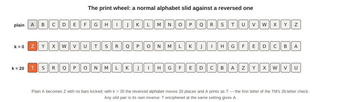
When the operator dials a plain letter P on the indicating disk, the typewheel turns with it. Its type faces are cut “in reverse order” (par. 5d), so the face that would print with no further movement is the letter at the opposite end of the alphabet: A prints Z, B prints Y, C prints X. The drive knob then turns the drum, the kicked bars drive the typewheel gear round k more letters, and the hammer strikes. The effect, in the manual’s words, “is that of sliding a normal-alphabet sequence against reversed normal alphabet” (par. 18). Numbering the letters A = 0 to Z = 25,
C = (25 − P + k) mod 26.
A count of 26 brings the typewheel right round to where it started and therefore acts like 0; a count of 27 acts like 1 — a detail the German analysts noted and a modern simulator must reproduce (Pokorny, TICOM I-175, p. 2: “26 bars protruding equal 0 bar, 27 bars equal 1 bar in effect”).
Subtracting from 25 rather than adding is what makes the machine reciprocal. Solving the formula for P gives P = (25 − C + k) mod 26 — the same formula with the letters swapped. If the receiving machine is set the same way, it is at the same count k on the same letter, and dialling the cipher letter prints the plain letter. That is why the encipher–decipher knob does not change the cipher at all. It changes only the printing: “Five-letter cipher groups are obtained only when the encipher-decipher knob is set in the encipher position” (par. 13a), and on deciphering a stop prevents the letter Z from being printed.
3.6.1 The reproducing disk
Because the reproducing disk is on the same shaft and is also lettered in reverse, the first letter visible in its window after each cycle is the letter just printed. If the tape or the ink pad ran out, the operator could keep working and copy the result from the disk, one letter per cycle (pars. 5c, 22b).
3.7 Printing, Spacing and Counting
The last parts of the cycle are bookkeeping, but they shaped how the machine was used.
Printing. The print arm, with a hard-rubber hammer clamped in its teeth, is pulled forward suddenly by its spring at the end of each cycle, when the printing cam on the drum shaft releases it. The hammer strikes the tape against the inked typewheel (par. 22d). An ink pad in a small holder keeps the typewheel inked.
Word spaces. The M-209 has no space key. The operator enciphers a Z between words. When the C–D knob is at D, a cam on its shaft pushes a print-arm stop forward; a small pin on the typewheel shaft, offset from the letter Z, meets that stop whenever Z is to be printed, and “a blank space appears on the tape” (par. 22e). Deciphered text therefore comes out in words, with any genuine Z lost: “Such a word as ORGANIZED will appear in clear text as ORGANI ED, but the missing letter can easily be supplied from the context” (par. 13b). The convention has a price: Z is by far the commonest plain letter, which an attacker can exploit (Volume 10).
Five-letter groups. A five-letter cam on the intermediate gear shaft (figure 8) advances the tape an extra space after every fifth letter while enciphering, so the cipher text comes off the machine already in groups. It works only if the letter counter starts at zero, which is why the manual makes zeroizing the counter step 3 of every encipherment (par. 10b(3)).
The letter counter. The counter records every letter up to 9999. It is not just a tally: it is how an operator recovers from a mistake. Having found that, say, the first 20 letters of a message deciphered correctly, he turns the counter back to 20 with the reset knob, which turns the key wheels back with it, and resumes at the 21st letter without starting again (par. 14). The counter also pins down which wheel holds a mis-set pin, by the spacing of the errors it causes — a procedure Volume 9 uses to debug the replica.
Paper feed. A large cam on the drum shaft works a feed ratchet that advances the tape one letter per cycle; a paper-feed knob turns the rollers by hand (pars. 5e, 23).
3.8 One Letter Through the Machine
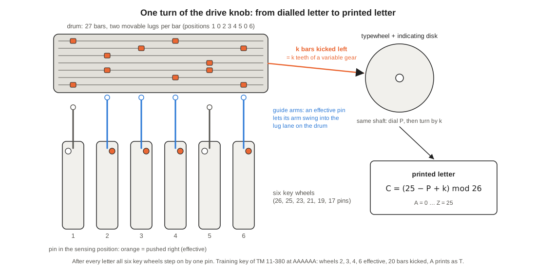
Here is the whole sequence for the first letter of the 26-letter check of the training key list printed in the 1944 manual — the key Volume 4 shows as a facsimile and the replica of Volume 9 is tested on. The operator has set the pins and lugs from the manual’s Tables I and II, turned all six wheels to A, zeroized the counter and set the knob to C.
- Dial. He turns the indicating disk to A. The typewheel turns with it; the type face now in printing position is Z.
- Sense. The drive knob starts to turn. The pins in play are P, O, N, M, L and K. In the training key, pin P on wheel 1 is ineffective, O on wheel 2 effective, N on wheel 3 effective, M on wheel 4 effective, L on wheel 5 ineffective and K on wheel 6 effective. Guide arms 2, 3, 4 and 6 swing forward.
- Kick. The training key’s 27 bars are set (bar 1 first) 3-6, 0-6, 1-6, 1-5, 4-5, 0-4 four times, 2-0 ten times, 2-5 twice and 0-5 six times. Every bar with a lug in lane 2, 3, 4 or 6 is kicked: bars 1–3 (lugs on 3 or 6), bar 5 (4), bars 6–9 (4) and bars 10–21 (2). Bar 4 (1-5) and bars 22–27 (0-5) are not. That is 20 bars.
- Count. The typewheel turns 20 letters, and the letter in printing position moves 20 places on from Z — A, B, C … — to T.
- Print and step. The hammer prints T; the five-letter cam notes one letter of the first group; the counter reads 0001; the feed cam steps all six wheels to BBBBBB; the drum locks.
The simulator gives the same result, and goes on (python3 m209_sim.py --key …, trace of the first three letters):
Table 2 — The simulator gives the same result, and goes on (python3 m209sim.py --key …, trace of the first three letters)
| Letter | Window | Pins in play | Wheels effective | Bars kicked k | Plain | Cipher |
|---|---|---|---|---|---|---|
| 1 | AAAAAA | PONMLK | 2, 3, 4, 6 | 20 | A | T |
| 2 | BBBBBB | QPONML | 4, 5 | 14 | A | N |
| 3 | CCCCCC | RQPONM | 5 | 10 | A | J |
The manual’s printed check begins TNJ — the first three letters of TNJUW AUQTK CZKNU TOTBC WARMI O — and the simulator reproduces all 26. (The same example, with the same count of 20 bars for the first letter, is worked in the Wikipedia article “M-209”, whose printed check string has one wrong letter; see the self-test notes in m209_sim.py.)
3.9 Why the Design Is Clever, and Where It Is Weak
The pin-and-lug principle packs a great deal into a small, light, purely mechanical box. It needs no electricity and no wiring; the whole key is set with a pencil point. One drive knob does everything: sensing, counting, printing, stepping, feeding and counting letters all hang off the same shaft, phased by cams. The six wheel sizes have no common factor, so the pattern of pins in play does not repeat for more than a hundred million letters. And the drum’s lug setting lets the key-list writer decide how much each wheel matters: a wheel facing twelve bars swings the output much more than one facing two.
The same mechanism contains the weaknesses that the codebreakers of Volume 5 found.
- The substitution is a slide. Whatever the key, each letter is enciphered by one of only 26 alphabets, all of them the same reversed alphabet slid to a different place. Two messages set from the same starting point share every slide, so subtracting one cipher text from the other removes the key completely (Volume 10 does it).
- The key is a count, and counts are uneven. Several patterns of active arms can give the same count, others give unique counts, and some counts occur much more often than others (Volume 7 measures it on the training key). The output is not uniformly random.
- Each wheel is a short loop. The pin in play on wheel 6 repeats every 17 letters, and its contribution to the count repeats with it. A long enough message, or a message with known text, lets an analyst sort the counts into 17, 19, 21, 23, 25 or 26 columns and read off which pins push the count up (Volume 10).
- Z for space. A cipher machine that asks its operator to encipher the same letter between every word gives an attacker a free crib.
None of this was news to the Army. The manual itself says the converter’s systems “can be solved, especially if a large volume of traffic is enciphered without changing the arrangement of the keying elements” (par. 7c), and Volume 4 shows the rules — daily key changes, fresh wheel settings for every message, no enciphered padding — that were meant to keep the weaknesses out of reach.
Next — Volume 4: In the Field — Smith-Corona, Key Lists and Signal Procedure. How 140,000 of these boxes were built in a typewriter factory, what came in the canvas case, how a key list was written and set, how a message was opened, enciphered and closed in procedure, and who carried the machine from North Africa to Korea.
Comments (0)