M-209 · Volume 8
M-209 — Volume 8 — Building an M-209 — Design and Printing
What open M-209 work already exists and why none of it is a printable machine; a design for a working mechanical replica built mainly from 3D-printed parts and stock steel — key wheels that grip 131 steel pins, a drum of 27 bars with sliding lug clips, a typewheel turned by kicked bars — and the materials, fasteners and printer settings to make it
8.1 About This Volume
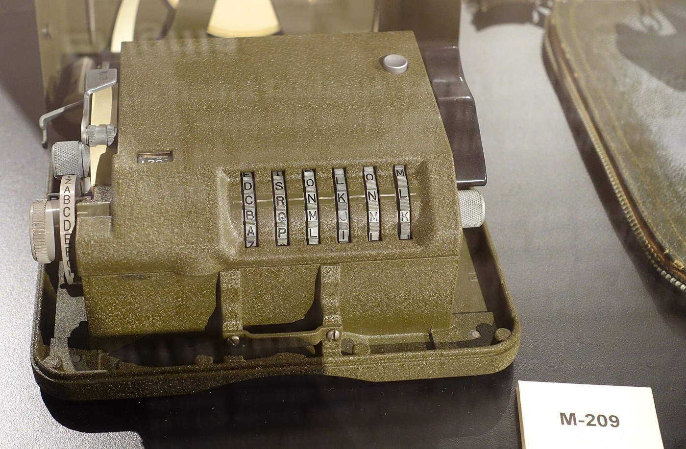
This is the first of the two build volumes. Its subject is a working mechanical M-209: a box in which a turn of a knob senses six pins, kicks a variable number of drum bars, turns a letter wheel by that number and steps six key wheels — and which, set to a key list, gives exactly the same letters as a wartime machine set to the same key. Volume 9 assembles it, sets a key and tests it against the unit’s simulator. Volume 10 uses it.
The volume runs in the order a builder needs it. It starts with a survey of what has already been published, because the first rule of a replica is not to redraw what someone else has drawn better. It then states the design brief, describes each assembly — key wheels, guide arms, drum and lugs, typewheel, drive and stepping, frame — gives the materials, fasteners and print settings, and ends with an optional electronic version for anyone who wants the cipher without the machining.
Nothing here has been built yet. The design is a specification drawn from the 1944 manual’s description of the mechanism (Volume 3), the published dimensions of the original and the usual tolerances of a hobby printer. Where the account of the real build will go, the text carries a marker.
8.2 What Already Exists
A search of the main open-hardware and code repositories in October 2026 found a good deal of M-209 software, one remarkable 3D data set, and no printable machine.
Table 1 — What Already Exists
| Project | What it is | Use for this build |
|---|---|---|
| m209 by Brian Neal (github.com/gremmie/m209) | Python 3 simulator and key-list generator, MIT licence; its tests carry letter checks from a working machine | The unit’s simulator is checked against its test vectors |
| Practical Use of the M-209 by Mark J. Blair, NF6X (nf6x.net) | Owner’s guide to keying and operating a real M-209, with key lists and letter checks; key-table generator on GitHub (NF6X/m209-key-tables) | Operating procedure; test vectors |
| M-209 simulator by Dirk Rijmenants (ciphermachinesandcryptology.com) | Windows simulator with a graphical machine | Cross-check of the operator’s view |
| Virtual Hagelin M-209 by Martin Gillow (m209.virtualcolossus.co.uk) | Browser 3D simulation built in Blender and three.js from CT scans of a real machine, 2024 (i-programmer) | Animated view of the guide arms, drum and printer in motion; no downloadable model |
| 3D-Cipher CT scans, Deutsches Museum with Fraunhofer EZRT (Zenodo record 8141627) | Computed-tomography scan of the museum’s M-209 as DICOM image stacks, about 850 MB zipped, CC BY-SA 4.0 | Internal proportions: wheel and drum diameters, lug and bar sections, gear spacing |
| M209KnownPlaintextAttackML (CrypTool project, GitHub) | Machine-learning known-plaintext attack | Not needed for the build |
On the model-sharing sites the picture was empty. Printables returned no models for “m209” or “hagelin”; its “cipher machine” results were Enigma replicas. Thingiverse returned nothing for “hagelin cipher”, and its “m-209” results were unrelated objects. Hackaday.io’s project search could not be read without logging in, so a Hackaday project may exist that this survey missed. No open, printable, working M-209 was found.
That decides the approach. The replica is an original design, credited to no one else, but it borrows its proportions from the Deutsches Museum’s scan (whose inventory number is given as 2017-397 on Zenodo and 2019-397 on the museum’s project page) and its behaviour from the 1944 manual and Gillow’s animation, and it is tested against software whose authors had real machines.
8.3 The Design Brief
The replica has to do seven things.
- Hold a key. 131 pins that stay where they are set, two positions each, set by hand; 27 bars carrying 54 lugs, each lug movable to any of eight positions (1 0 2 3 4 5 0 6).
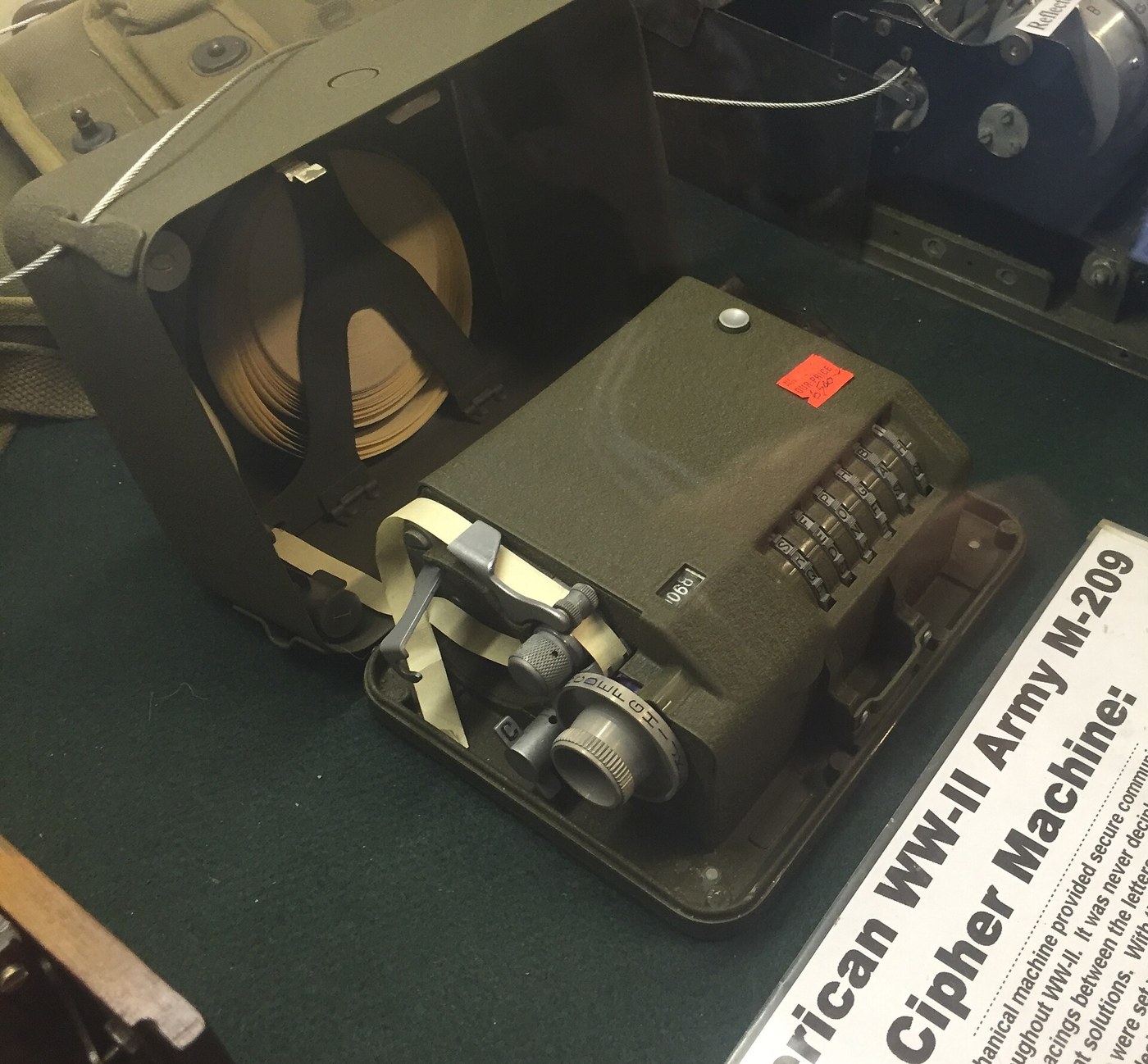
- Read the pins a fixed distance from the window. The pin in play on each wheel must be the one 15, 14, 13, 12, 11 or 10 places on from the letter at the bench mark (Volume 3). If this is wrong, nothing else matters: the machine will not match the manual’s 26-letter check.
- Count correctly. A bar must move once if either lug meets an active arm, and the typewheel must turn exactly one letter per moved bar, for every count from 0 to 27.
- Reverse the alphabet. The result must be C = (25 − P + k) mod 26: the output wheel lettered backwards relative to the input dial, on one shaft.
- Step after sensing. All six wheels advance one pin per letter, and only after the drum has finished reading the arms.
- Survive handling. Thousands of cycles at a moderate hand speed, and repeated re-keying.
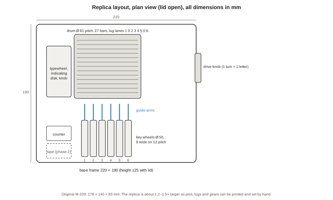
- Be printable. Every custom part fits a 220 × 220 mm bed, needs no support in the working areas, and tolerates ±0.15 mm.
Two things are deliberately left to a second phase: printing on tape and the drum lock interlock. The 1944 manual itself allowed an operator to work without tape by reading each result from the reproducing disk (par. 22b), and the first-phase replica works that way. A letter counter is included from the start, because it is cheap and because Volume 9 uses it to locate faults.
8.3.1 Scale
The original is 178 × 140 × 83 mm, and its pins are small: about 1 mm across, on a pitch of a few millimetres. Printed parts at that scale would be fragile and the pins impossible to set reliably. The replica is drawn at roughly 1.2 to 1.5 times the original in its working parts, giving a base of 220 × 190 mm and a height of about 125 mm with the lid closed. That keeps it a desk object, still recognisably a lunchbox, and lets every part be printed on a common bed.
8.4 The Key Wheels
Each key wheel is a sandwich of three rings on a common hub: two printed discs, A and B, each 4 mm thick and 50 mm in diameter, with a 1 mm ring of TPU (or cut silicone sheet) clamped between them by three M3 screws. A ring of axial holes on a 42 mm pitch circle carries the pins: 26 holes on wheel 1, down to 17 on wheel 6. The pin pitch along the circle therefore runs from 5.1 mm on wheel 1 to 7.8 mm on wheel 6 — the replica, like the original, keeps all wheels the same diameter and lets the pin spacing vary.
The pins are hardened steel dowel pins, 2 mm in diameter and 12 mm long (ISO 8734, m6). The holes in the printed discs are drawn at 2.0 mm and opened after printing with a 2.0 mm drill or reamer to a sliding fit; the hole in the TPU ring is drawn at 1.6 mm, so that the ring grips the pin. The grip is the detent. A pin pushed fully right stands 3 mm proud of disc B and is flush on the left; pushed fully left it stands 3 mm proud on the left. Nothing but friction limits the travel; the operator pushes each pin until its end is flush with one face, which is easy to feel and easy to check by eye, and Volume 9 checks every pin.
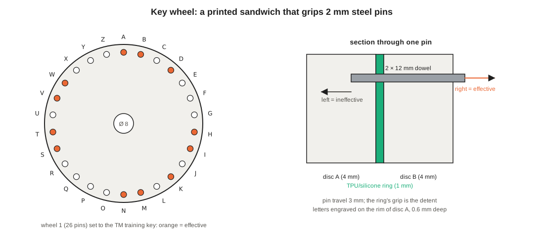
Letters are engraved 0.6 mm deep on the rim of disc A, at the same angular positions as the pins, and paint-filled; printing the rim face-up at 0.12 mm layers gives clean letters. The letters on wheels 2 and 3 skip W, and wheel 3 stops at X, exactly as on the original (Volume 3); a wheel lettered A–Y would key the machine wrongly while looking right.
Two features set the replica’s wheels apart from the original’s:
- The sensing position is marked. A small arrow on disc B at 15, 14, 13, 12, 11 or 10 places from each letter (the offset for that wheel) shows, when the wheel is off the shaft, which pin will be in play when that letter is at the bench mark. It costs nothing and prevents the commonest assembly error.
- Each wheel carries its own ratchet. Disc B has an N-tooth ratchet moulded on its inner face — 26 teeth on wheel 1, 17 on wheel 6 — so that one pawl stroke advances that wheel by exactly one pin, whatever its size. This replaces the original’s set of intermediate gears of different sizes (Volume 3) with a simpler arrangement that a printer handles better.
The wheels turn freely on a fixed 8 mm ground steel shaft, each on a printed bushing bored to 8.1 mm. A light leaf-spring detent on each wheel — a printed PETG finger pressing on a 26- to 17-lobe detent ring — holds the wheel square to the bench mark between steps and gives the click the manual describes (“each key wheel upon coming into place will click audibly”, par. 10b(4)).
8.5 The Guide Arms
Six guide arms, printed in PETG, pivot on a 4 mm steel rod between the wheels and the drum. Each has three working faces:
- a follower nose that bears on the left face of its wheel at the sensing position, under the wheel;
- a kicking ramp at the other end, which stands in its lug lane on the drum when the arm is forward;
- a hook for a small extension spring (0.4 mm wire, 4 mm outside diameter, about 15 mm long) that pulls the arm toward the drum.
The logic follows the original exactly (TM 11-380, par. 20). A pin pushed left — ineffective — stands proud of the wheel’s left face and holds the follower nose back, so the arm stays clear of the drum. A pin pushed right — effective — leaves the left face flush, the nose drops into the gap, the spring pulls the arm forward, and the ramp enters the lug lane. The nose is shaped with a shallow V so that when the wheels step, the next pin rides it smoothly back rather than catching it.
A printed comb between the arms keeps them on their 12 mm pitch and stops them twisting under the side load of a lug.
8.6 The Drum and the Lugs
The drum is the part that most needs care, because it does the counting.
End discs and bars. Two printed end discs, 92 mm in diameter, are fixed to an 8 mm drum shaft running in two 688ZZ bearings (8 × 16 × 5 mm) in the side frames. Between them run 27 bars, each a flat PETG plate 4.5 mm thick, 10 mm deep and about 92 mm long, standing radially in slots in the end discs. The slots are 4 mm longer than the bars’ tongues, so each bar can slide 4 mm along the axis. As in the original, the bars occupy about two-thirds of the circumference: their centres sit on an 81 mm pitch circle at a spacing of 360° ÷ 40.5 ≈ 8.9°, so that the 254.5 mm circumference of the pitch circle, divided into 40.5 bar spaces, puts them 6.28 mm apart — the circular pitch of a module 2 gear. The remaining third of the circumference is empty, and the machine uses the time that gap takes to pass the arms to step the wheels and print.
Lug clips. The original’s lugs are small sliding blocks that snap into holes along the bar. The replica’s are lug clips: U-shaped PETG clips that straddle the 4.5 mm bar, with a printed spring tongue that snaps into V-notches cut in the bar’s outer edge. Each bar has eight notches at the original’s eight positions, in the original’s order 1 0 2 3 4 5 0 6, at 0, 6, 12, 24, 36, 48, 54 and 60 mm from the left — so the six working positions sit on the 12 mm wheel pitch, under the six guide arms, and the two zero positions sit half a pitch away, where no arm can reach. Each bar carries two clips. Setting the lugs from a key list is then a matter of sliding clips with a fingertip until they click, as on the original; no tool is needed.
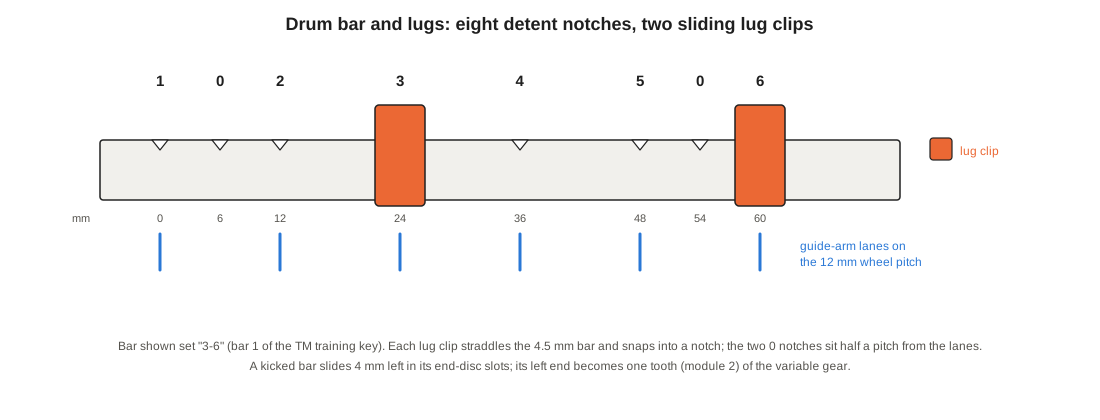
Kicking and counting. As the drum turns, a lug clip in the lane of a forward arm meets the arm’s ramp and is pushed 4 mm to the left, taking its bar with it. A bar with two clips facing two forward arms is pushed by the first and is already left when it reaches the second: it moves once. That is the “counts once” rule of Volume 3, enforced by geometry rather than logic. The left end of a kicked bar now projects 4 mm beyond the left end disc into the plane of the typewheel gear, a 26-tooth, module 2 spur gear (pitch diameter 52 mm) on the typewheel shaft. Each projecting bar end passes through the gear’s mesh like a single tooth of a rack and turns the gear on by one tooth: one twenty-sixth of a turn, one letter. Bars that were not kicked pass behind the gear without touching it.
Retracting. After the bars have passed the typewheel gear, a fixed printed ramp on the left side frame — the retractor — pushes every kicked bar back 4 mm to the right before it comes round to the arms again. A light friction ring (an O-ring in a groove on each end disc, bearing on the bar tongues) keeps unkicked bars from drifting.
8.7 The Typewheel Shaft
The typewheel shaft is a 6 mm steel rod in two 686ZZ bearings (6 × 13 × 5 mm). On it, from the left, are fixed:
- the setting knob, knurled;
- the indicating disk, 60 mm in diameter, lettered A–Z in normal order on its rim, read against an index mark on the lid;
- the reproducing disk, 46 mm in diameter, lettered in reverse order (Z, Y, X … A), read through a window in the lid: this is where the phase-1 machine shows its result;
- a detent wheel with 26 V-notches and a spring plunger (an M6 ball-nose spring plunger, or a 3 mm steel ball on a compression spring in a printed housing), which centres the shaft on each letter;
- the typewheel gear, 26 teeth, module 2.
The letters on the two disks are placed so that, with no bars kicked, the reproducing disk shows Z when the indicating disk shows A, Y for B, and so on. Every kicked bar then moves both disks one more letter. The result in the window is C = (25 − P + k) mod 26.
8.7.1 Phase 2: the printer
A printed typewheel with raised type can be added to the same shaft later: TPU 95A for the type faces, which takes ink better than PLA and survives a hammer, inked by a felt roller charged with stamp-pad ink. A hammer on a spring-loaded arm, released by a cam on the drum shaft at the end of each cycle, strikes 10 mm paper tape against the typewheel, as in the original (TM 11-380, par. 22d). The Z-space stop of the original — a pin on the typewheel shaft that meets a stop when deciphering, so that Z prints as a blank (par. 22e) — and the five-letter spacing cam can be added at the same time. The printer is the least proven part of the design and is kept separate so the cipher machine works without it.
8.8 Drive and Stepping
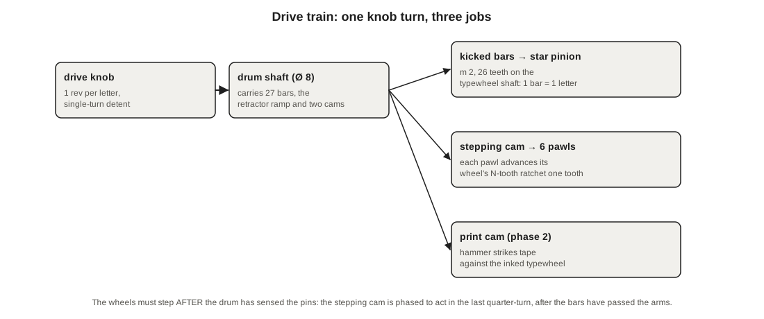
The drive knob is fixed to the right end of the drum shaft and turns it 1:1. A spring-loaded ball dropping into a notch in the right end disc gives a definite home position at the end of each turn; the operator turns until it clicks, exactly as on the original (“turn the drive knob until it locks”, par. 10c(2)).
The wheels must step after the drum has sensed the pins, never during. The replica uses the empty third of the drum for this. A stepping cam on the drum shaft, phased to act while the gap in the bars is passing the arms, rocks a pawl bar carrying six spring pawls, one per wheel, through one stroke. Each pawl pushes its wheel’s ratchet on by one tooth. Because each wheel’s ratchet has exactly as many teeth as the wheel has pins, one stroke is always exactly one pin, for all six wheels at once. The same rocking motion advances the letter counter, a commercial five-digit mechanical stroke counter screwed under the front of the lid, by one count.
The pawls also do the job of the original’s ratchets (TM 11-380, par. 19c): with the drive knob at home, a wheel can be turned forward by hand to set it, the pawl clicking over its teeth. Like the original, the replica sets a wheel in one direction only.
Phase 2 adds the drum lock of the original (par. 21c): a lock arm that drops between two teeth of the typewheel gear at the end of each turn and holds the drum until the indicating disk has been moved. It is a refinement, not a necessity; its absence only means the operator must not turn the knob twice without changing the letter.
8.9 Frame, Lid and Case
The frame is a printed base tray with two side plates, joined by M3 screws into heat-set inserts. The side plates carry the bearings for the drum and typewheel shafts and the clamps for the key-wheel shaft and guide-arm rod. A printed inner lid closes over the mechanism, with six windows over the wheel rims, a white bench mark beside them, the index for the indicating disk and the reading window for the reproducing disk. It hinges at the back and lifts to set pins and lugs — as on the original, the key is set with the lid up, and the lid is closed for operation. An outer cover, printed in two halves to fit the bed, closes the box.
Olive-drab PLA matches the original’s crinkle paint well enough; the lid can carry an engraved data plate reading, honestly, “REPLICA”.
8.10 Materials, Fasteners and Bought Parts
8.10.1 Bill of materials
Table 2 — Bill of materials
| Item | Specification | Qty |
|---|---|---|
| Key-wheel pins | Steel dowel pin, ISO 8734, 2 × 12 mm | 131 (buy 150) |
| Key-wheel shaft, drum shaft | Ground steel rod, 8 mm, cut to 130 mm | 2 |
| Typewheel shaft | Ground steel rod, 6 mm, cut to 110 mm | 1 |
| Guide-arm rod, pawl-bar rod | Steel rod, 4 mm, cut to 90 mm | 2 |
| Drum bearings | 688ZZ, 8 × 16 × 5 mm | 2 |
| Typewheel bearings | 686ZZ, 6 × 13 × 5 mm | 2 |
| Wheel-sandwich and frame screws | M3 socket head cap screw, ISO 4762, 8, 12 and 16 mm | about 60 |
| Threaded inserts | M3 heat-set brass insert, 5–6 mm long | about 40 |
| Retaining clips | E-clip (DIN 6799) for 8, 6 and 4 mm shafts | 12 |
| Guide-arm and pawl springs | Extension spring, 0.4 mm wire, 4 mm OD, about 15 mm | 12 (buy an assortment) |
| Detents | 3 mm steel ball + light compression spring, or M6 ball-nose spring plunger | 2 |
| Drum friction rings | O-ring, nitrile, sized to the end-disc groove | 2 |
| Pin-grip rings | TPU 95A printed, or 1 mm silicone sheet cut | 6 |
| Letter counter | Mechanical stroke counter, 5 digits, lever actuated | 1 |
| Phase 2 | 10 mm paper tape; stamp-pad ink; felt for the ink roller | — |
Prices and suppliers are left out on purpose: every item is a common stock part, and the costs will be recorded when the parts are bought.
8.10.2 Printed parts
About 120 printed parts: 12 wheel discs, 6 TPU rings, 6 wheel bushings and detent fingers, 6 guide arms and a comb, 2 drum end discs, 27 bars, 54 lug clips (print 60), the retractor ramp, the typewheel-shaft disks and gear, the stepping cam, pawl bar and 6 pawls, the drive knob, the base, side plates, inner lid and outer cover.
8.11 Printer Settings
All settings are for a 0.4 mm nozzle on a well-calibrated printer. The working parts are small, and the difference between a smooth machine and a jammed one is mostly in the first three rows of this table.
Table 3 — Printer Settings
| Part group | Material | Layer | Walls | Infill | Orientation and notes |
|---|---|---|---|---|---|
| Wheel discs, detent rings | PETG | 0.12 mm | 4 | 40 % gyroid | Flat, engraved rim face up; ream pin holes to 2.0 mm after printing |
| Drum bars | PETG | 0.16 mm | 4 (solid) | 100 % | On edge, length along X, so layer lines run the length of the bar; deburr notches |
| Lug clips | PETG | 0.12 mm | 3 | 100 % | Flat, tongue in the plane of the bed so it flexes across layers, never between them |
| Gears, cams, ratchet teeth | PETG | 0.12 mm | 4 | 60 % | Flat; check the module 2 tooth form on a test piece first |
| Guide arms, pawls | PETG | 0.16 mm | 4 | 60 % | Flat, so the spring hooks are not across layer lines |
| Pin-grip rings, phase-2 type | TPU 95A | 0.16 mm | 2 | 100 % | Slow (20–25 mm/s); holes drawn 1.6 mm |
| Base, side plates, lids, cover | PLA or PLA+ | 0.20 mm | 3 | 20 % gyroid | Bearing seats drawn at nominal and pressed; inserts set at 220 °C |
PETG is chosen for every part that flexes, slides or is struck, because it is tougher and less brittle than PLA and slides better against itself; PLA is fine for the stiff frame. No working part needs supports. Holes for steel rod are drawn 0.1 mm oversize for running fits (8.1 mm in the wheel bushings) and at nominal size where a press fit is wanted.
Before any of this, print a tolerance coupon: a small plate with a 2.0 mm pin hole, a 1.6 mm TPU-grip hole, an 8.1 mm bushing bore, one notched bar section with a lug clip, and a pair of module 2 teeth. Adjust hole compensation until the dowel slides, the clip clicks firmly, and the 8 mm rod turns freely. Volume 9 starts there.
8.12 Design Risks
Three parts of the design carry most of the risk, and the build order of Volume 9 tests each before anything depends on it.
- Pin grip. If the TPU ring grips too lightly, pins drift when the follower noses push them; too hard, and setting 131 pins becomes a chore. The coupon decides the hole size.
- Bar-end meshing. Each kicked bar end must turn the typewheel gear exactly one tooth, never zero and never two, at hand speed. The detent wheel on the typewheel shaft corrects small errors; a large one means the bar ends are not on the 81 mm pitch circle or the gear is not on module 2. A count test with known lug settings (Volume 9) catches it.
- Stepping phase. If the stepping cam acts before the last bar has passed the arms, the last few bars read the next letter’s pins. The symptom is subtle — the machine works, but disagrees with the simulator on some letters — and the 26-letter check exposes it.
8.13 Sidebar: An M-209 on a Microcontroller
The cipher itself is simple enough to run on any small microcontroller, and an electronic M-209 makes a useful companion to the mechanical one: a second machine to send to. The core of the unit’s simulator — the M209 class in m209_sim.py, about eighty lines — uses nothing outside standard Python and runs under MicroPython on a Raspberry Pi Pico with only the command-line part left out (MicroPython has no argparse). Six rotary encoders with push switches make good key wheels, a small OLED shows the window letters and the result, and a 26-key keypad or a rotary encoder stands in for the indicating disk. Key lists can be typed in or loaded from a file. Such a machine reproduces the 26-letter check and every example in this series — it is the simulator in a box — but it is not a replica, and it teaches nothing about the mechanism. Its value is as a reference to test the mechanical machine against, letter by letter, away from a computer.
Next — Volume 9: Building an M-209 — Assembly, Setting the Key and Testing. The tolerance coupon, then the drum, the typewheel, the wheels and the arms, each tested before the next hides it; setting the manual’s own training key list; the 26-letter check; and what the letter counter and a periodic garble reveal when the replica disagrees with the simulator.
Comments (0)